
MEC-380 · Lesson 6 of 12 · 22 min
Rotating unbalance and balancing
Unbalance is the most common cause of vibration in rotating machinery, and the only one that every pump has to some degree. No impeller is perfectly symmetric: castings vary in wall thickness, machining leaves small eccentricities, and keys, keyways and coupling hubs add their own asymmetry. In service, wear, corrosion and fouling make things worse. Tidewater balances every impeller on a balancing machine before assembly, and Lucie now wants Owen to understand what the balance tolerance means, how it is achieved, and how to balance a complete rotor in its own bearings when a shop balance is not enough. A batch of TP-80 impellers from a new foundry has just arrived, and the first one runs at 4.2 mm/s on the test stand, three times the normal value.
Static and dynamic unbalance
An unbalance can be described by an equivalent mass m_u at radius e from the axis, giving an unbalance \(U = m_u e\), usually expressed in g·mm. Equivalently, a rotor of mass M whose centre of mass is displaced by a distance e from the axis has an unbalance \(U = Me\), and e is called the specific unbalance. Rotating at ω, the unbalance produces a radial force \(F = U\omega^2\) that rotates with the shaft, so a fixed sensor sees a sinusoidal vibration at exactly running speed, 1×.
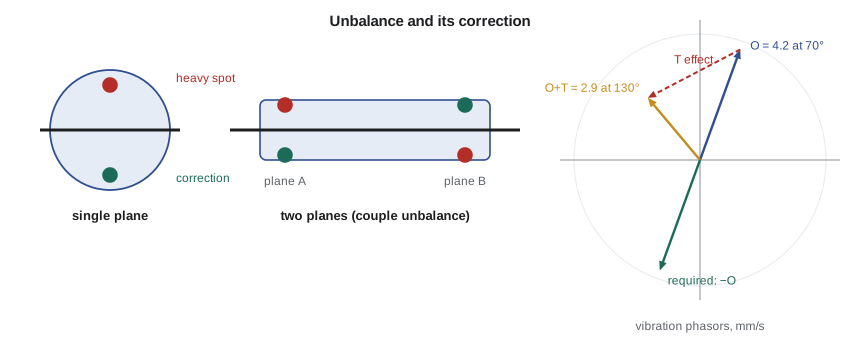
Unbalance comes in two forms that matter for correction. Static unbalance is a displacement of the centre of mass from the axis; it can be detected without rotating, because the rotor rolls to put its heavy side down on knife edges. Couple unbalance is a tilt of the principal axis of inertia relative to the shaft axis, which leaves the centre of mass on the axis but produces a rocking moment when the rotor spins. A general, or dynamic, unbalance is a combination of the two. A narrow rotor such as a single impeller, whose length is small compared with its diameter, can be treated as having static unbalance only and corrected in a single plane. A long rotor, such as a motor armature or the multistage TM-4 rotor, needs correction in at least two planes.
Balance quality grades
International practice expresses balance tolerances by the balance quality grade of ISO 21940-11, which replaced the long-used ISO 1940-1 without changing the grade system. The grade G is the product of the permissible specific unbalance e_per and the maximum service angular speed, expressed in mm/s:
Grades are spaced by a factor of 2.5: G40, G16, G6.3, G2.5, G1 and finer. The standard's tables suggest grades for classes of machine. Pump impellers, fans and general machinery parts are traditionally balanced to G6.3; machine-tool drives, turbines, compressors and electric motor rotors with special requirements to G2.5. Purchasers often specify a finer grade than the table suggests, and petroleum and chemical industry pump standards such as API 610 call for tighter tolerances for critical-service pumps. Because e_per is inversely proportional to speed, a rotor that runs twice as fast must have half the centre-of-mass offset to meet the same grade, which keeps the unbalance force growing only in proportion to speed rather than to its square.
# Balance tolerance for the TP-80 impeller and influence-coefficient balancing in one and two planes
import math, cmath
def pol(a, deg): return cmath.rect(a, math.radians(deg))
def show(z): return f"{abs(z):.2f} at {math.degrees(cmath.phase(z)) % 360:.0f} deg"
# 1. Permissible residual unbalance from the balance quality grade (ISO 21940-11)
m_imp = 9.5                        # impeller mass, kg
n = 1760; w = 2 * math.pi * n / 60
for G in (6.3, 2.5):
    e = G * 1000 / w               # permissible specific unbalance, g mm/kg (= um)
    U = e * m_imp
    print(f"Grade G{G}: e = {e:.1f} um, U_per = {U:.0f} g mm, i.e. {U/120:.2f} g at a 120 mm radius")
U = 6.3 * 1000 / w * m_imp * 1e-6  # kg m
print(f"Force from the G6.3 limit at 1,760 rpm: {U*w**2:.1f} N; at 3,560 rpm it would be {U*(2*math.pi*3560/60)**2:.1f} N")

# 2. Single-plane balancing on the test stand (readings: velocity mm/s with phase from a key-phasor)
V0 = pol(4.2, 70)                  # original vibration
trial = pol(20.0, 0)               # trial mass 20 g at 0 deg on the 120 mm radius
V1 = pol(2.9, 130)                 # vibration with the trial mass
alpha = (V1 - V0) / trial          # influence coefficient, mm/s per g
corr = -V0 / alpha                 # correction that cancels V0
print(f"\nSingle plane: influence coefficient {show(alpha)} (mm/s per g)")
print(f"Correction mass {show(corr)} (g); remove the trial mass")
print(f"Predicted residual {abs(V0 + alpha*corr):.2f} mm/s; correction unbalance {abs(corr)*120:.0f} g mm")

# 3. Two-plane balancing of the TM-4 multistage rotor (planes A and B, bearings 1 and 2)
V = [pol(5.6, 40), pol(3.8, 205)]                  # original readings at bearings 1, 2
TA = pol(30, 0); TB = pol(30, 0)                   # trial masses, g
VA = [pol(3.1, 95), pol(4.4, 230)]                 # readings with trial in plane A
VB = [pol(6.9, 25), pol(2.0, 150)]                 # readings with trial in plane B
a11 = (VA[0] - V[0]) / TA; a21 = (VA[1] - V[1]) / TA
a12 = (VB[0] - V[0]) / TB; a22 = (VB[1] - V[1]) / TB
det = a11 * a22 - a12 * a21
WA = (-V[0] * a22 + V[1] * a12) / det              # solve [a]{W} = -{V}
WB = (-V[1] * a11 + V[0] * a21) / det
print(f"\nTwo-plane corrections: plane A {show(WA)} g, plane B {show(WB)} g")
R1 = V[0] + a11 * WA + a12 * WB; R2 = V[1] + a21 * WA + a22 * WB
print(f"Predicted residuals: bearing 1 {abs(R1):.2f}, bearing 2 {abs(R2):.2f} mm/s")Grade G6.3: e = 34.2 um, U_per = 325 g mm, i.e. 2.71 g at a 120 mm radius Grade G2.5: e = 13.6 um, U_per = 129 g mm, i.e. 1.07 g at a 120 mm radius Force from the G6.3 limit at 1,760 rpm: 11.0 N; at 3,560 rpm it would be 45.1 N Single plane: influence coefficient 0.19 at 208 deg (mm/s per g) Correction mass 22.55 at 42 deg (g); remove the trial mass Predicted residual 0.00 mm/s; correction unbalance 2707 g mm Two-plane corrections: plane A 52.03 at 18 deg g, plane B 42.59 at 14 deg g Predicted residuals: bearing 1 0.00, bearing 2 0.00 mm/s
For the 9.5 kg TP-80 impeller at 1,760 rpm, G6.3 allows a specific unbalance of 34.2 µm and a residual unbalance of 325 g·mm, equivalent to 2.7 g at a 120 mm radius. The force at full speed is 11.0 N, which is the force used in Lessons 4 and 5. At G2.5 the allowance falls to 129 g·mm. The program also shows why tolerances matter more on faster machines: the same 325 g·mm at the TM-4's 3,560 rpm would produce 45 N, four times as much.
Balancing machines
In a shop balancing machine, the rotor spins on a mandrel in two supports fitted with sensors, and the machine reports the amount and angular position of the unbalance in each correction plane. Soft-bearing machines run above the resonance of their flexible supports and measure displacement; hard-bearing machines run below the resonance of stiff supports and measure force. Either way, the machine has been calibrated so that its reading converts directly to g·mm and degrees. Correction is made by removing material (drilling or grinding the impeller shroud) or adding it (welding or bolting a weight). Tidewater grinds the outer edge of the impeller back shroud, never the vanes.
A shop balance has limits. The mandrel and its fit to the impeller bore add their own eccentricity: a fit clearance of 25 µm can shift a 9.5 kg impeller by up to 12 µm, more than a third of the G6.3 allowance. Keys and coupling hubs must be represented by half-keys according to the convention in ISO 21940-32, or the assembled rotor will not match the balanced parts. And some rotors are flexible, bending at their service speed, so that a balance at low speed does not hold at high speed (Lesson 11). For these reasons, critical machines are sometimes balanced in place, in their own bearings at full speed, using the influence coefficient method.
Field balancing in a single plane
Field balancing uses a vibration sensor on a bearing and a once-per-revolution reference, usually a reflective tape and an optical tachometer, which together give the amplitude and phase of the 1× vibration. The method assumes linearity: the vibration is proportional to the unbalance, so the effect of any added mass can be predicted once the effect of one known mass is measured.
The procedure has three runs. The first records the original vibration \(\bar V_0\), a phasor of amplitude and phase. A trial mass \(\bar T\) of known size and angle is added, and the second run records \(\bar V_1\). The influence coefficient is
where \(\bar W\) is the correction mass and angle that cancels the original vibration. The trial mass is removed and the correction installed for the third, check run. The bars denote complex numbers: every quantity has a magnitude and a phase, and the arithmetic is the phasor arithmetic of Lesson 1.
For the new impeller on the stand, the original reading is 4.2 mm/s at 70°. A 20 g trial mass at 0° changes it to 2.9 mm/s at 130°. The program gives an influence coefficient of 0.19 mm/s per gram at 208° and a correction of 22.6 g at 42°, which predicts zero residual vibration. That correction represents an unbalance of about 2,700 g·mm, eight times the G6.3 limit: the foundry's castings are badly off-centre. Owen corrects the impeller in the shop to confirm the diagnosis, then Lucie rejects the batch.
Worked problem
Choosing a trial mass
A trial mass must be large enough to change the vibration clearly, typically by 25 to 30 percent in amplitude or phase, but not so large that the machine shakes dangerously. A rule of thumb is that the trial mass should produce a force of about 10 percent of the rotor weight. Find this mass for the 9.5 kg impeller at 1,760 rpm and a radius of 120 mm.
Show solution
- Rotor weight: 9.5 × 9.81 = 93.2 N; 10 percent is 9.3 N.
- Required unbalance: \(U = F/\omega^2 = 9.3/184.3^2 = 2.74 \times 10^{-4}\) kg·m = 274 g·mm.
- Mass at 120 mm: 274/120 = 2.3 g.
Answer: The rule suggests a trial mass of about 2.3 g, much less than the 20 g Owen used. On a rotor this badly out of balance, a larger trial mass was needed to change the reading clearly. Judgement, and the vibration level the machine can tolerate during the trial run, decide.
Two-plane balancing
For a long rotor, unbalance in each plane affects both bearings. With two correction planes A and B and two bearings 1 and 2, four influence coefficients are needed, found from two trial runs (one trial mass in each plane). The corrections satisfy two simultaneous complex equations:
where α_ij is the vibration at bearing i per unit mass in plane j. The program solves this for the TM-4 multistage rotor, whose original readings are 5.6 mm/s at bearing 1 and 3.8 mm/s at bearing 2. The corrections are 52 g at 18° in plane A and 43 g at 14° in plane B. With more bearings or more speeds than planes, the equations are solved by least squares, which is how large turbine rotors are balanced. The method fails if the influence coefficients are nearly dependent (the matrix is nearly singular), which happens if the correction planes are too close together; that is why planes are chosen near the ends of the rotor.
When high 1× vibration is not unbalance
Lucie's warning is that not every 1× problem is unbalance, and balancing the wrong problem wastes time and can damage the machine. Bent shafts, eccentric coupling bores and misalignment also produce 1×, as does resonance, which amplifies a small unbalance into a large vibration. Signs that it is not simple unbalance include phase that is different in the horizontal and vertical directions by much other than 90°, high axial vibration, large 2× components, or vibration that changes with load or temperature rather than with speed. In the hospital pump of Lesson 5 and the field pump of Lesson 2, the impellers were within tolerance; resonance, not unbalance, was the problem.
Common mistakes
MistakeAdding the correction at the angle of the original reading.
InsteadUse the influence coefficient; the response lags the unbalance by an unknown phase.
MistakeLeaving the trial mass in place.
InsteadRemove it, unless the calculation explicitly includes it as part of the correction.
MistakeBalancing a rotor that is near resonance without checking linearity.
InsteadNear resonance, phase changes rapidly with speed; balance at a stable speed.
MistakeUsing a single plane for a long rotor.
InsteadLong rotors have couple unbalance and need two planes.
MistakeBalancing a coupling without the half-key convention.
InsteadFollow ISO 21940-32 so parts balanced separately match when assembled.
Summary and key terms
- Unbalance U = m_u e produces a rotating force Uω² and a 1× vibration.
- Static unbalance is corrected in one plane; couple and dynamic unbalance need two.
- ISO 21940-11 grades define e_per ω = G; pump impellers are usually balanced to G6.3.
- The TP-80 impeller allows 325 g·mm at G6.3, an 11 N force at 1,760 rpm.
- Field balancing uses influence coefficients: α = (V₁ − V₀)/T and W = −V₀/α, all as phasors.
- The new foundry's impeller had about 2,700 g·mm, eight times the limit, so the batch was rejected.
- Unbalance
- The product of an equivalent unbalanced mass and its radius from the axis.
- Specific unbalance
- Unbalance divided by rotor mass; the offset of the centre of mass.
- Static unbalance
- Unbalance that displaces the centre of mass from the axis.
- Couple unbalance
- Unbalance that tilts the principal axis without displacing the centre of mass.
- Balance quality grade
- The product of permissible specific unbalance and service angular speed, in mm/s.
- Correction plane
- A plane in which mass is added or removed to balance a rotor.
- Trial mass
- A known mass added to measure the effect of unbalance at a correction plane.
- Influence coefficient
- The vibration change per unit unbalance at a correction plane.
- Key phasor
- A once-per-revolution reference used to measure phase.
- Half-key convention
- The convention for representing keys when balancing parts separately.
Practice problems
Work each problem on paper first, then reveal the answer to check.
A 25 kg fan rotor runs at 1,180 rpm. Find U_per for G6.3.
Show answer
e = 6300/123.6 = 51 µm; U = 1,275 g·mm.
What force does a 10 g mass at 200 mm produce at 3,000 rpm?
Show answer
0.002 × 314.2² ≈ 197 N.
V₀ = 3.0 at 0°; with 10 g at 0°, V₁ = 4.5 at 0°. Find the correction.
Show answer
α = 0.15 at 0°; W = 20 g at 180°.
Why are grades spaced by 2.5 rather than 2?
Show answer
A factor of 2.5 gives a convenient decade sequence: G16, G6.3, G2.5, G1.
In the program, change the trial run to 5.0 mm/s at 80°. What correction results?
Show answer
Recompute α = (V₁ − V₀)/T; the correction is about 74 g at 130°, showing that a small change of reading can mean a very different correction.
Name two signs that high 1× vibration is not unbalance.
Show answer
High axial vibration with large 2×, or vibration that changes with load or temperature.
Lesson quiz · 5 questions
Score 60% or more to complete this lesson.
Create a free account to save your progress, take quizzes and earn a certificate.