
MEC-380 · Lesson 11 of 12 · 21 min
Rotordynamics and critical speeds
The purchasing department has found a cheaper forging for the TM-4 multistage pump shaft. The production shaft is 65 mm in diameter at the impellers; the proposed one is 55 mm, lighter and easier to machine, and the stress calculations from MEC-360 still pass. Farah is not convinced, and she asks Owen to check the effect on the rotor's first critical speed, the speed at which the shaft's own bending resonance is excited by its unbalance. A machine that runs near a critical speed can vibrate violently even when well balanced, and it may rub its wear rings and seize. Rotordynamics, the study of vibrating rotating shafts, is a specialized field, but its basic ideas follow directly from Lessons 4, 6 and 10.
The Jeffcott rotor
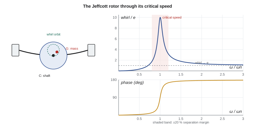
The simplest rotor model, studied by Föppl and by Jeffcott in the late nineteenth and early twentieth centuries, is a disk of mass m at the middle of a massless flexible shaft of lateral stiffness k, running in rigid bearings. The disk's centre of mass is offset from the shaft's geometric centre by a small eccentricity e. When the shaft spins at ω, unbalance makes the shaft bow and its centre whirl around the bearing axis in a circle of radius r_w. For steady synchronous whirl with damping ζ, the whirl amplitude is
This is the rotating-unbalance curve of Lesson 4. The speed at which the whirl peaks, ω_n, is the critical speed: the natural frequency of the shaft's lateral bending, excited by its own unbalance. The program's table shows the behaviour. Below the critical speed, the shaft bows toward the heavy spot (the phase lag is small). At the critical speed the whirl is limited only by damping, ten times the eccentricity for ζ = 0.05, and the phase lag is 90°. Above it, the phase lag approaches 180°: the heavy spot moves toward the inside of the whirl orbit, and at high speeds the disk spins about its own centre of mass, with the shaft centre whirling at a radius approaching e. This self-centring above the critical speed is why some machines, such as steam turbines, are designed to run above their first critical speed, passing through it quickly during run-up.
Stiff and flexible rotors
A rotor running well below its first critical speed is called stiff, or rigid: its bending deflection under unbalance is small, and a low-speed shop balance holds at full speed. A rotor running above one or more critical speeds is flexible: its deflected shape changes with speed, and it may need multi-plane balancing at several speeds (Lesson 6). Most industrial pumps are designed as stiff rotors, with the first dry critical speed above the running speed. The TP-80, with its short overhung shaft, has a first critical speed of several thousand rpm, comfortably above 1,760 rpm. Multistage pumps like the TM-4, with long bearing spans carrying several impellers, are where critical speeds become a design problem.
Estimating the first critical speed
For a shaft carrying several masses, Rayleigh's method of Lesson 2 extends naturally. Using the static deflection curve under the weights of the masses as the assumed mode shape gives
where δ_i is the static deflection at mass i. Like all Rayleigh estimates, it is slightly high. A second classical formula, due to Dunkerley, combines the frequencies the shaft would have with each mass alone, \(1/\omega_1^2 \approx \sum 1/\omega_i^2\), and gives a lower bound. The true value lies between the two, and when they agree within a few percent, either is good enough for a first check. Detailed rotordynamic analysis, required by industry standards for critical-service pumps, uses finite element rotor models with bearing and seal stiffness and damping coefficients, and computes damped natural frequencies and responses as functions of speed.
# Rotordynamics: the Jeffcott rotor and the first critical speed of the TM-4 multistage pump
import math
# 1. Jeffcott rotor: disk with eccentricity e on a massless shaft, synchronous whirl amplitude
e = 20e-6                                  # mass eccentricity, m
zeta = 0.05
print(" speed/critical   whirl amplitude/e   phase deg")
for r in (0.5, 0.8, 0.95, 1.0, 1.05, 1.2, 2.0, 4.0):
    amp = r**2 / math.sqrt((1 - r**2)**2 + (2 * zeta * r)**2)
    ph = math.degrees(math.atan2(2 * zeta * r, 1 - r**2))
    print(f"{r:14.2f} {amp:19.2f} {ph:11.0f}")
print("Well above the critical speed the disk spins about its own centre of mass (amplitude -> e).")

# 2. TM-4 rotor: first lateral critical speed by Rayleigh's method and by Dunkerley's formula
g = 9.81; E = 200e9; rho = 7850
L = 1.10                                   # bearing span, m
imps = [(0.36, 4.2), (0.48, 4.2), (0.62, 4.2), (0.74, 4.2)]   # impeller positions (m) and masses (kg)
def critical(d, n_el=44):
    I = math.pi * d**4 / 64
    masses = list(imps) + [((j + 0.5) * L / n_el, rho * math.pi * d**2 / 4 * L / n_el) for j in range(n_el)]
    def defl(x):                           # static deflection at x from all weights (simply supported)
        tot = 0.0
        for a, m in masses:
            P = m * g; b = L - a
            if x <= a: tot += P * b * x * (L**2 - b**2 - x**2) / (6 * E * I * L)
            else:      tot += P * a * (L - x) * (2 * L * x - x**2 - a**2) / (6 * E * I * L)
        return tot
    num = sum(m * defl(a) for a, m in masses); den = sum(m * defl(a)**2 for a, m in masses)
    w_ray = math.sqrt(g * num / den)
    inv = 0.0                              # Dunkerley: 1/w^2 = sum of 1/w_i^2 for each mass alone
    for a, m in masses:
        b = L - a; k = 3 * E * I * L / (a**2 * b**2)
        inv += m / k
    return w_ray * 60 / (2 * math.pi), 60 / (2 * math.pi) / math.sqrt(inv)
n_run = 3560
for d in (0.050, 0.055, 0.060, 0.065, 0.070):
    nr, nd = critical(d)
    print(f"Shaft {d*1000:.0f} mm: Rayleigh {nr:6.0f} rpm, Dunkerley {nd:6.0f} rpm (lower bound); "
          f"margin above running speed {(nr - n_run)/n_run:6.1%}")
# 3. Wet critical speed: wear-ring and balance-drum fluid stiffness (Lomakin effect) adds support stiffness
d = 0.065; nr, _ = critical(d)         # the production shaft
k_shaft = (2 * math.pi * nr / 60)**2 * (sum(m for _, m in imps) + 0.5 * rho * math.pi * d**2 / 4 * L)
for k_fluid in (0.0, 2e6, 5e6):
    m_eff = k_shaft / (2 * math.pi * nr / 60)**2
    n_wet = math.sqrt((k_shaft + k_fluid) / m_eff) * 60 / (2 * math.pi)
    print(f"  added fluid stiffness {k_fluid/1e6:3.0f} MN/m: first critical about {n_wet:5.0f} rpm")
# 4. Oil whirl in the journal bearings appears just below half running speed
print(f"\nOil whirl would show at about 0.42-0.48 x running speed: {0.42*n_run/60:.1f}-{0.48*n_run/60:.1f} Hz;"
f" it becomes whip if running speed exceeds twice the first critical ({2*nr:.0f} rpm)") speed/critical whirl amplitude/e phase deg
0.50 0.33 4
0.80 1.74 13
0.95 6.63 44
1.00 10.00 90
1.05 7.51 134
1.20 3.16 165
2.00 1.33 176
4.00 1.07 178
Well above the critical speed the disk spins about its own centre of mass (amplitude -> e).
Shaft 50 mm: Rayleigh 3002 rpm, Dunkerley 2919 rpm (lower bound); margin above running speed -15.7%
Shaft 55 mm: Rayleigh 3498 rpm, Dunkerley 3398 rpm (lower bound); margin above running speed -1.7%
Shaft 60 mm: Rayleigh 4007 rpm, Dunkerley 3889 rpm (lower bound); margin above running speed 12.6%
Shaft 65 mm: Rayleigh 4525 rpm, Dunkerley 4388 rpm (lower bound); margin above running speed 27.1%
Shaft 70 mm: Rayleigh 5050 rpm, Dunkerley 4894 rpm (lower bound); margin above running speed 41.9%
added fluid stiffness 0 MN/m: first critical about 4525 rpm
added fluid stiffness 2 MN/m: first critical about 5132 rpm
added fluid stiffness 5 MN/m: first critical about 5927 rpm
Oil whirl would show at about 0.42-0.48 x running speed: 24.9-28.5 Hz; it becomes whip if running speed exceeds twice the first critical (9050 rpm)The program models the TM-4 rotor as a simply supported shaft with a 1.10 m bearing span, four 4.2 kg impellers and the shaft's own mass in 44 elements. For the production 65 mm shaft, Rayleigh's method gives a first dry critical speed of 4,525 rpm and Dunkerley's formula 4,388 rpm, so the true value lies between them: 23 to 27 percent above the 3,560 rpm running speed. For the proposed 55 mm shaft, the estimate falls to about 3,500 rpm, within 2 percent of running speed: the pump would run on its critical speed. Shaft stiffness scales with d⁴, while the rotor mass falls much less because the impellers do not change, so the 15 percent smaller diameter lowers the critical speed by about 23 percent. Farah's suspicion is confirmed, and the cheaper forging is rejected.
Wet and dry critical speeds
The calculation above gives the dry critical speed, with the pump empty and the rotor supported only by its bearings. In a running pump, the close clearances at the wear rings, the balance drum and the interstage bushings carry a pressure drop, and the flow through them produces a centring force proportional to displacement, called the Lomakin effect. These annular seals act as extra bearings with significant stiffness and damping. The program shows the effect of adding a fluid stiffness of 2 or 5 MN/m at the impellers: the first critical rises from 4,525 rpm to about 5,130 and 5,930 rpm. The wet critical speed of a multistage pump can therefore be well above the dry one. The effect weakens as the clearances wear, because the stiffness falls with increasing clearance. A pump designed to rely on the Lomakin effect for its separation margin can drift toward its critical speed as it wears, which is why pump standards ask for both dry and wet analyses and consider worn clearances. The program's fluid stiffness values are illustrative; real values come from seal analysis or testing.
Separation margins
Standards for rotating machinery specify a separation margin between the operating speed range and any critical speed, so that the machine does not run in the region of high amplification. API 610, for centrifugal pumps in petroleum, petrochemical and natural gas service, and its companion guidance on rotordynamics, set margins that depend on the amplification factor of the mode; a well-damped mode needs less margin than a sharply peaked one. Margins of 15 to 25 percent are typical in practice, and a value of 20 percent is a common design target. Owen's report quotes the margin for each shaft diameter: 27 percent for the 65 mm shaft against the dry critical, more against the wet; −2 percent for the 55 mm shaft. For the TM-4, which is sold on variable-speed drives up to 3,800 rpm for some boiler applications, the 65 mm shaft's margin against 3,800 rpm is still 19 percent dry, which is why Farah keeps it.
Worked problem
Passing through a critical speed
A steam turbine-driven pump on another site is designed to run at 1.4 times its first critical speed, with ζ = 0.08 for the mode. What is the whirl amplitude at running speed and while passing through the critical speed, relative to the eccentricity e?
Show solution
- At r = 1.4: \(r_w/e = 1.96/\sqrt{(1 - 1.96)^2 + (0.224)^2} = 1.96/0.986 = 1.99\).
- At r = 1: \(r_w/e = 1/(2 \times 0.08) = 6.25\).
- With e of 20 µm, the shaft whirls 40 µm at speed and 125 µm while passing through the critical.
Answer: Running above a critical speed is acceptable if the run-up is quick and clearances accommodate the transient whirl. Stiff-rotor pumps avoid the problem altogether.
Oil whirl and other self-excited instabilities
Not all rotor vibration is forced by unbalance. A shaft in a lightly loaded plain journal bearing can be driven into a self-excited whirl by the bearing's own oil film. The oil in the clearance travels at about half the journal's surface speed, and when the journal is displaced, the pressure field produces a cross-coupled force perpendicular to the displacement, which can feed energy into a forward whirl at a frequency of about 0.42 to 0.48 times running speed. This oil whirl is often stable in amplitude, but if running speed exceeds about twice the first critical speed, the whirl frequency locks onto the critical speed and becomes oil whip, a violent instability that does not go away when speed is raised further. For the TM-4, whose journal bearings were designed in MEC-360, whirl would appear at 25 to 28 Hz, and whip would require speeds above about 9,000 rpm, far above its operating range. Pressure-dam, tilting-pad and other bearing designs are used where whirl is a risk. Other self-excited mechanisms, such as internal friction and aerodynamic cross-coupling in compressors, are beyond this course.
Gyroscopic effects and Campbell diagrams
A spinning disk that tilts as the shaft bends generates gyroscopic moments, which stiffen forward whirl modes and soften backward ones, so the natural frequencies of a rotor change with speed. A Campbell diagram plots the natural frequencies of the rotor against speed, together with lines for the excitation frequencies, 1×, 2× and vane pass. Intersections of the 1× line with natural frequency curves are the critical speeds. For the TM-4, the impellers are narrow and close to the bearings, so gyroscopic effects are small, and the simple model is adequate. On overhung fans and turbines with large disks far from the bearings, they can be large, and a Campbell diagram from a rotor model is essential.
Common mistakes
MistakeUsing only the dry critical speed for a multistage pump.
InsteadConsider the wet critical with fluid stiffness, and the effect of worn clearances.
MistakeAssuming a lighter shaft is always better for vibration.
InsteadCheck the critical speed: a smaller diameter lowers stiffness faster than mass.
MistakeExpecting a low-speed balance to hold on a flexible rotor.
InsteadFlexible rotors may need balancing at speed in several planes.
MistakeTreating sub-synchronous vibration near 0.45× as unbalance.
InsteadIt is a sign of oil whirl or another self-excited instability.
MistakeRelying on the separation margin without considering amplification.
InsteadMargins depend on how sharply the mode is peaked; use the standard's criteria.
Summary and key terms
- The Jeffcott rotor's whirl r_w/e follows the rotating-unbalance curve; it peaks at the critical speed and tends to e above it.
- Rayleigh's method gives an upper estimate and Dunkerley's formula a lower estimate of the first critical speed.
- The 65 mm TM-4 shaft has a first dry critical of about 4,400 to 4,500 rpm, a margin of about 25 percent over 3,560 rpm.
- A 55 mm shaft would put the critical at about 3,500 rpm, within 2 percent of running speed, so it was rejected.
- Fluid stiffness at annular seals (the Lomakin effect) raises the wet critical speed but weakens as clearances wear.
- Oil whirl appears at about 0.42 to 0.48× running speed and turns into whip above about twice the first critical speed.
- Critical speed
- A speed at which a rotor's natural frequency is excited by its unbalance.
- Jeffcott rotor
- A disk on a massless flexible shaft, the simplest rotordynamic model.
- Whirl
- The orbital motion of a shaft centre about the bearing axis.
- Stiff rotor
- A rotor running well below its first critical speed.
- Flexible rotor
- A rotor running above one or more critical speeds.
- Dry critical speed
- A critical speed calculated without fluid forces at seals and wear rings.
- Wet critical speed
- A critical speed including the stiffness and damping of fluid-filled clearances.
- Lomakin effect
- The centring stiffness produced by pressure-driven flow through an annular seal.
- Separation margin
- The difference between an operating speed and a critical speed, as a percentage.
- Oil whirl
- A self-excited sub-synchronous whirl in plain journal bearings.
Practice problems
Work each problem on paper first, then reveal the answer to check.
A disk of 20 kg sits on a shaft with lateral stiffness 8 MN/m. Find the critical speed.
Show answer
ω = 632 rad/s, about 6,040 rpm.
At twice the critical speed with ζ = 0.05, find r_w/e.
Show answer
4/√(9 + 0.04) = 1.33.
Rayleigh gives 4,525 rpm and Dunkerley 4,388 rpm. What is a sensible design value?
Show answer
About 4,400 to 4,500 rpm; using the lower bound is conservative for a machine below its critical.
What separation margin does the 65 mm shaft have at 3,800 rpm?
Show answer
(4,525 − 3,800)/3,800 ≈ 19 percent, dry.
In the program, change the bearing span to 1.25 m. What happens to the 65 mm critical speed?
Show answer
It falls, to roughly 3,600 rpm, showing how sensitive critical speeds are to span.
Why might a multistage pump's vibration rise slowly over years of service without any change in balance?
Show answer
Wear-ring clearances open, the Lomakin stiffness falls and the wet critical speed drops toward running speed.
Lesson quiz · 5 questions
Score 60% or more to complete this lesson.
Create a free account to save your progress, take quizzes and earn a certificate.