
LVT-220 · Lesson 9 of 12 · 20 min
Network racks, patching and documentation
Room 6A at Kellerman was finished in LVT-130: three racks, patch panels A to H with 348 certified ports, horizontal and vertical managers, a tray ring overhead and a 24-strand fibre panel for the backbone. What it does not yet have is switches, power for them, and the patch cords that connect each outlet to a switch port. Those turn a cabling system into a working network, and how they are installed decides whether the room stays tidy and maintainable for the next fifteen years or becomes the tangle of cords that every technician has seen in older buildings. This lesson covers mounting network equipment, power and cooling in the room, patching from the port map and the records that go with it.
Rack layout for active equipment
Sanjay's rack elevations, from LVT-120, already placed the switches. The usual layout puts each switch directly below or between the patch panels it serves, so that patch cords run a short distance through a horizontal manager. Brightwater's access switches are 1U, 48-port units, four of them now with the PoE switch added in week one, so the elevation pairs each switch with two 24-port panel rows. The fibre panel and the uplink switch, or the uplink ports on the access switches, sit near the top of rack 1 where the backbone enters. The uninterruptible power supply, heavy and with batteries, goes at the bottom.
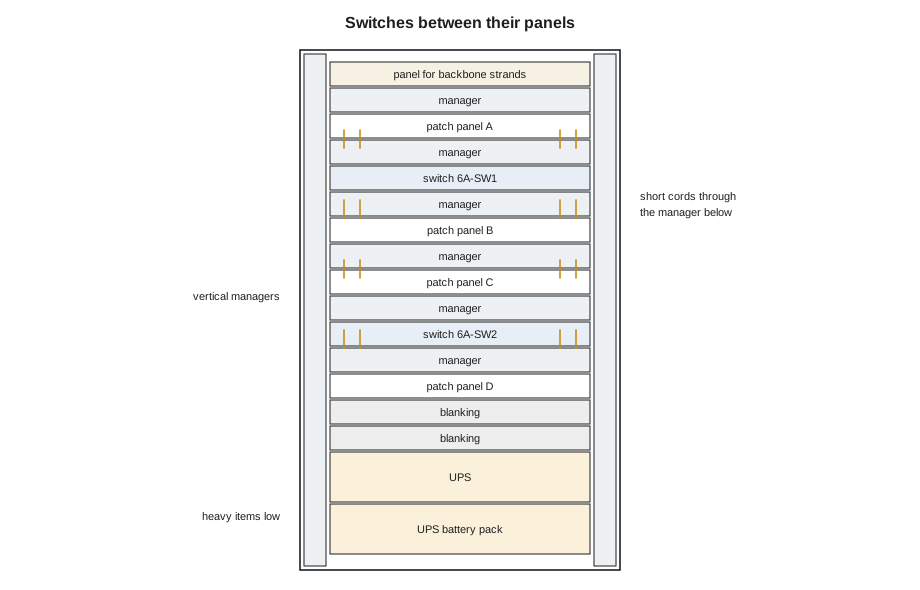
Network switches move air from front to back or back to front, and the rack must let them. The airflow direction is printed on the switch and set by the fan and power supply modules ordered; it must match the room's arrangement, so that switches draw cool air from the room and exhaust warm air where the room's cooling expects it. Blanking panels fill empty rack units so warm exhaust does not loop back to the intakes. In a small room like 6A with one cooling unit, Sanjay's design puts the cold air at the front of the racks and the switches are ordered front-to-back.
Switches are mounted with the rails or ears supplied, on all four posts where the rack and switch allow, with cage nuts in the correct holes. A 1U switch with full PoE power supplies weighs 7 to 9 kg (15 to 20 lb) and should not hang on two front ears in a four-post rack, where it can sag and stress the patch cords. The UPS, much heavier, goes on rails or a shelf at the bottom, and two people lift it.
# Rack space check for room 6A rack 2: does the equipment fit?
items = [("patch panel D", 1), ("horizontal manager", 1), ("switch 6A-SW2", 1), ("horizontal manager", 1),
         ("patch panel E", 1), ("horizontal manager", 1), ("patch panel F", 1), ("horizontal manager", 1),
         ("switch 6A-SW3", 1), ("horizontal manager", 1), ("patch panel G", 1), ("blanking panels", 8),
         ("UPS", 3), ("UPS battery pack", 3), ("power strips (rear, zero U)", 0)]
used = sum(u for _, u in items)
print(f"rack units used: {used} of 45, free: {45 - used}")
for name, u in items:
    if u:
        print(f"  {u:2d} U  {name}")
# heat left in the room: switch electronics plus power supply losses on the PoE delivered
switches, electronics_w, poe_w, supply_eff = 4, 120, 820, 0.90
heat = switches * electronics_w + poe_w * (1 / supply_eff - 1)
print(f"PoE sent out on the cables: {poe_w} W; heat left in room 6A: about {heat:.0f} W")rack units used: 25 of 45, free: 20 1 U patch panel D 1 U horizontal manager 1 U switch 6A-SW2 1 U horizontal manager 1 U patch panel E 1 U horizontal manager 1 U patch panel F 1 U horizontal manager 1 U switch 6A-SW3 1 U horizontal manager 1 U patch panel G 8 U blanking panels 3 U UPS 3 U UPS battery pack PoE sent out on the cables: 820 W; heat left in room 6A: about 571 W
The heat line deserves a comment. The four switches delivering about 820 W of PoE do not release all of that in the room; most of the power leaves on the cables and is used, and turned into heat, by the access points and cameras on the floor. What stays in the room is the switch's own electronics and the losses in its power supplies. The cooling design counts both, and Sanjay's numbers for 6A were checked by the mechanical engineer.
Power for the network
Every switch in 6A needs power from a circuit the electrician installs, through a power strip in the rack, usually through the UPS. Brightwater's PoE switches have two power supplies each, and each supply goes to a different strip, so a single failed strip or supply does not take the switch down. The electrician installs the receptacles and circuits; the crew mounts the power strips the design names, connects the equipment and labels every cord at both ends with the strip and outlet number. Mains power is outside the low-voltage scope, and the crew does not open or modify power strips or receptacles.
The UPS keeps the switches, and through them every PoE device on the floor, running through a short power cut and long enough for an orderly shutdown in a longer one. That makes the UPS the battery backup for the cameras, door controllers and access points as well. The runtime is the battery energy divided by the load, adjusted for the UPS's efficiency and for the batteries' age. Brightwater's specification asks for 30 minutes at full load, and the load is mostly PoE.
# UPS runtime estimate for room 6A
battery_wh = 1300        # usable battery energy, from the UPS data sheet
efficiency = 0.92
aging = 1.25             # design for batteries near end of life, as in LVT-110
switch_w = 4 * 120       # switch electronics
poe_w = 820            # PoE actually drawn by devices on the floor
load = switch_w + poe_w
runtime_min = battery_wh * efficiency / aging / load * 60
print(f"load {load} W: runtime about {runtime_min:.0f} minutes with aged batteries")
for extra in (0, 300, 600):
    l2 = load + extra
print(f" with {extra:3d} W more PoE: {battery_wh * efficiency / aging / l2 * 60:4.0f} minutes")load 1300 W: runtime about 44 minutes with aged batteries with 0 W more PoE: 44 minutes with 300 W more PoE: 36 minutes with 600 W more PoE: 30 minutes
The estimate shows how a future change to PoE load quietly shortens battery runtime. When Brightwater later adds displays powered by Class 8 PoE, the runtime will fall below the specification unless batteries are added. Maya notes the calculation in the job file so that the next change is checked against it.
Patching from the port map
The port map is the bridge between the cabling records and the network design. For each outlet, it names the patch panel port, the switch and switch port it connects to, the VLAN that port is configured for, and the device the outlet serves. Omar produces it from his switch configuration, using the outlet labels from Cobalt Line's as-built records. Maya patches from it, one port at a time, and marks each line as done. Lesson 3 showed what happens when a cord goes to the wrong port: the device lands on the wrong VLAN.
Patch cords should be the right length, not the nearest length. A cord that is too long has to be coiled or looped, and loops in the managers become the tangle that makes rooms unmaintainable. A cord that is too short pulls on both jacks. With switches directly below their panels, most cords in 6A are 0.3 m (1 ft) or 0.6 m (2 ft) long. The design names the cords: Category 6A, factory-made, from the cabling manufacturer's warranty system, in colours that mean something. Brightwater uses blue for staff and voice, yellow for access points, red for cameras and door access, and green for building systems and management, so that a glance at a panel shows what is where.
# Port map: generate patching instructions for one switch from the plan
port_map = [
    # (outlet, panel port, switch port, vlan, device)
    ("6A-C13", "C13", 13, 40, "CAM-6-03"),
    ("6A-C14", "C14", 15, 40, "CAM-6-04"),
    ("6A-D01", "D01", 25, 30, "AP-6-01"),
    ("6A-D02", "D02", 26, 30, "AP-6-01 second port"),
    ("6A-D17", "D17", 41, 50, "DC-6-02"),
    ("6A-A05", "A05", 5, 10, "desk 6-A05 phone and computer"),
]
cord = {10: "blue", 20: "blue", 30: "yellow", 40: "red", 50: "red", 60: "green", 99: "green"}
seen = set()
for outlet, panel, port, vlan, device in sorted(port_map, key=lambda r: r[2]):
    assert port not in seen, f"switch port {port} used twice"
    seen.add(port)
print(f"panel {panel:4s} -> 6A-SW2 port {port:2d} VLAN {vlan:2d} {cord[vlan]:6s} cord {device}")panel A05 -> 6A-SW2 port 5 VLAN 10 blue cord desk 6-A05 phone and computer panel C13 -> 6A-SW2 port 13 VLAN 40 red cord CAM-6-03 panel C14 -> 6A-SW2 port 15 VLAN 40 red cord CAM-6-04 panel D01 -> 6A-SW2 port 25 VLAN 30 yellow cord AP-6-01 panel D02 -> 6A-SW2 port 26 VLAN 30 yellow cord AP-6-01 second port panel D17 -> 6A-SW2 port 41 VLAN 50 red cord DC-6-02
Cords are dressed as they go in: through the horizontal manager directly below, in a neat sweep with no tight bends, held with hook-and-loop straps, never cable ties, and with nothing crossing the front of a panel that someone will need to reach. Unused switch ports are left empty, not filled with spare cords, and many network teams disable them as lesson 11 explains. Unused panel ports are not patched at all; a cord with nothing on the far end is a cord someone will one day spend an hour tracing.
Labels and records
Every patch cord in 6A gets a label at each end, with the panel port at the switch end and the switch port at the panel end, or with a single identifier that the records link to both, following the TIA-606 scheme from LVT-120. Switches get their names on the front and rear. Power cords get the strip and outlet number. The labels are printed, not handwritten, and placed so they can be read without moving cords.
The records Cobalt Line hands over grow with this course. LVT-130 delivered the certification reports for every link. Now the commissioning sheets add, for every connected outlet: the switch and port, the VLAN, the device name, model, serial number, MAC address, IP address, firmware version, PoE class and power drawn, link speed, the date and who did it, and the result of the application test. Together with the port map and rack elevations, they are what the owner's network team needs to run the floor without calling the installer.
| Record | Contents | Who keeps it after handover |
|---|---|---|
| Certification reports | Test results for each permanent link, from LVT-130 | Owner's facilities team |
| Port map | Outlet, panel port, switch port, VLAN, device | Owner's network team |
| Commissioning sheets | Device identity, address, firmware, power, speed, test result | Owner's network and security teams |
| Rack elevations as built | Equipment positions, power connections | Owner's facilities and network teams |
| IP plan as built | Every fixed and reserved address actually used | Owner's network team |
| Photos | Each device as mounted, with its label | Owner and Cobalt Line's job file |
Change control
On an occupied network, a patch cord is a change. Moving a cord can take a device off one VLAN and put it on another, or connect something new to a live network. Owners such as St. Brendan's and the Riverside school board require that every change be requested, approved and scheduled, and the crew follows that process exactly, even for a single cord. On a new floor like Brightwater's, before handover, the crew patches from the port map without separate approval, but once the floor is in service, every move goes through Lucia's change requests. Maya learns to update the port map and commissioning sheet on the day of each change, not at the end of the job, because a record that is a week out of date is already wrong.
Worked problem
A port map that does not match the room
During patching, Maya finds that the port map lists outlet 6A-F09 on switch 6A-SW3 port 33, VLAN 30, for access point AP-6-12. Port 33 already has a cord in it, from outlet 6A-F11, which the map lists on port 35. What should she do?
Show solution
- Do not move the existing cord to make room; it may be in use.
- Check the label on the existing cord and the map's revision date: the cord was patched from an earlier revision.
- Ask Omar which revision is current. He confirms the current map: 6A-F11 belongs on port 35.
- With his confirmation, move 6A-F11's cord to port 35, patch 6A-F09 into port 33, check both devices come up on the right VLANs, and update the sheet.
Answer: Both access points come online in the controller. Maya notes the correction, the time and Omar's confirmation on the commissioning sheet.
Common mistakes
MistakeUsing long cords and coiling the slack in the managers.
InsteadUse cords of the right length for each run.
MistakePatching unused panel ports to switch ports.
InsteadPatch only the outlets in the port map that serve a device.
MistakeMounting a heavy PoE switch on two front ears in a four-post rack.
InsteadUse rails or four-post mounting so it cannot sag.
MistakePlugging both power supplies of a switch into the same strip.
InsteadConnect each supply to a different strip, as the design shows.
MistakeUpdating records at the end of the job.
InsteadUpdate the port map and sheets on the day of each change.
Summary and key terms
- Switches go next to the patch panels they serve so cords are short; heavy equipment goes at the bottom.
- Airflow direction, blanking panels and the room's cooling must agree.
- Dual power supplies go to different strips; the UPS backs up every PoE device through the switches.
- Patch only from the current port map, with cords of the right length, category and colour.
- Label cords, switches and power connections; record every connected device's identity, address, power and test result.
- On occupied networks, every patch change goes through the owner's change process and is recorded on the day.
- Port map
- The table linking each outlet to its panel port, switch port, VLAN and device.
- Blanking panel
- A cover that fills an empty rack unit to keep airflow in order.
- UPS
- Uninterruptible power supply: keeps equipment running from batteries during power loss.
- Change control
- The owner's process for requesting, approving and scheduling changes.
- Commissioning sheet
- The record of each device's identity, settings and test results.
Practice problems
Work each problem on paper first, then reveal the answer to check.
Why is a heavy UPS mounted at the bottom of a rack?
Show answer
To keep the rack stable and make lifting safer.
A switch has two power supplies. How should they be connected?
Show answer
To two different power strips, so one strip failing does not take the switch down.
An outlet in the panel has no device. Should it be patched?
Show answer
No; patch only outlets that serve a device in the port map.
Why does adding PoE load matter to the UPS?
Show answer
It increases the load and shortens battery runtime.
Lesson quiz · 5 questions
Score 60% or more to complete this lesson.
Create a free account to save your progress, take quizzes and earn a certificate.