
HSE-374 · Lesson 7 of 12 · 21 min
Temporary bracing and structural stability
Every finished building has a system that keeps it standing up straight against wind and other sideways loads. In the classroom wing of the Prairie Gate Community Centre, that system was two braced bays of diagonal steel tubes on each side of the building, connected by the concrete-filled metal deck floors that act as stiff horizontal plates, called diaphragms. In the gymnasium, it was the tilt-up concrete walls connected to the roof deck. In the library, it was steel rod bracing hidden in the walls and the CLT floor and roof panels acting as diaphragms. On the day the first columns went up, none of those systems existed yet. Until they did, the only things keeping the frame upright were the anchor rods, the connections already made and the temporary bracing that Sanjay Mehta had designed.
Structural collapse during erection is less common than falls, but when it happens it is often catastrophic: whole bays fold over, sometimes taking several workers with them. This lesson covers how a frame gets its stability, why it is unstable during erection, how temporary bracing works, who designs it, and the rules about removing it.
How a finished frame stands up
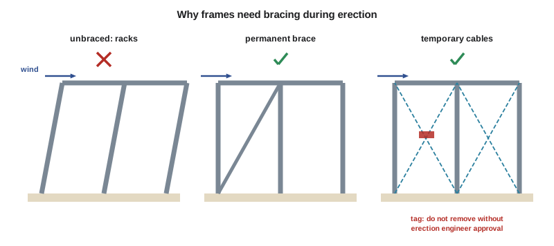
Gravity loads, the weight of the building and its contents, go straight down through beams and columns to the foundations. Lateral loads, from wind and earthquakes, push sideways. A frame of beams and columns connected with simple bolted shear connections, like most of the Prairie Gate Community Centre, has almost no resistance to lateral load on its own; push it sideways and it racks over like a parallelogram. Something must stiffen it.
- Braced frames. Diagonal members in certain bays turn rectangles into triangles, which cannot rack.
- Moment frames. Rigid beam-to-column connections resist rotation, so the frame resists racking through bending.
- Shear walls and cores. Concrete or masonry walls, such as elevator and stair cores, resist lateral load like stiff vertical plates.
- Diaphragms. Floors and roofs, such as concrete on metal deck or CLT panels, act as horizontal plates that collect lateral loads and deliver them to the braced frames, moment frames or walls.
The engineer of record designs these systems for the completed building and shows them on the structural drawings. The drawings must make clear which members and assemblies provide lateral stability, because until they are complete and connected, the frame relies on something else.
Why frames are unstable during erection
During erection, the lateral system is incomplete in several ways at once. The permanent braces may not all be installed, or may be installed but not fully bolted or welded. The deck that will form the diaphragm may be partly laid and not fastened. Concrete on the deck has not been placed. Tilt-up walls are standing on temporary braces and not yet connected to the roof. Connections are bolted with only two wrench-tight bolts. And the partly built frame catches wind on members, decking bundles and any material landed on it.
Erection loads can also be larger than the loads the finished building sees in certain spots. A bundle of deck landed on a few joists, a crane load swung into a column, a connector forcing a misfit, or a concrete bucket set down on a fresh deck can put large local loads on parts of the frame that are not yet complete.
Temporary bracing
Temporary bracing gives the frame the stability it needs until the permanent system takes over. It is usually designed by the erector's erection engineer and installed by the raising gang as the steel goes up.
- Cable bracing. Wire rope cables run diagonally across bays or from columns to ground anchors, with turnbuckles or ratchets to tension them and plumb the frame. Cable bracing is light and quick but only works in tension, so it is used in pairs.
- Struts and knee braces. Rigid members that can push as well as pull, used where cables cannot be anchored.
- Temporary moment connections. Extra bolts or plates that stiffen selected connections until the permanent bracing is in.
- Guying to the ground. Cables from the top of columns to deadmen or anchors in the ground.
Plumbing up, the work of bringing columns plumb and the frame square, is done with the temporary bracing. The cables are tightened and adjusted until the columns are within the erection tolerance, then locked off. A frame should be plumbed and its bracing tensioned before the bolting-up crew does the final tightening, because final tightening locks the frame in whatever shape it is in.
CSA S16, the Canadian design standard for steel structures, whose erection clause covers erection loads, temporary bracing and erection tolerances makes the erector responsible for temporary bracing to keep the structure stable during erection, unless the contract assigns it elsewhere. Under the general duties in Manitoba's Act and regulation, the employer must keep a partly built structure from collapsing and follow the engineer's design and instructions for it. On the Prairie Gate Community Centre, every temporary brace was shown on Sanjay Mehta's stamped erection bracing drawings, with its size, anchorage, tension and removal stage.
Limits on how far erection can get ahead
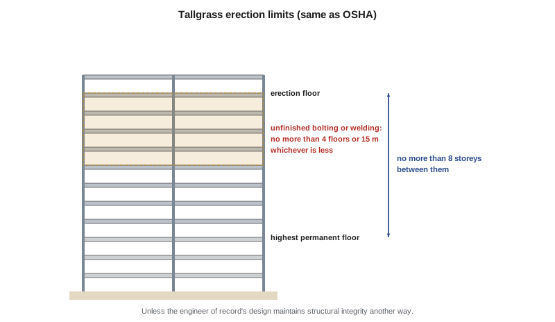
The higher a frame goes before its floors and permanent connections are complete, the more it depends on temporary measures. Tallgrass applies the same limits on its Manitoba jobs that OSHA sets in the United States, unless the engineer of record's design shows that the structure's integrity is maintained some other way: no more than eight storeys between the erection floor and the highest permanent floor, and no more than four floors or 15 m (48 ft), whichever is less, of unfinished bolting or welding above the foundation or the highest permanently secured floor. The Prairie Gate Community Centre was only three storeys, so the first limit never came into play, but the second meant the bolting-up crew had to keep close behind the connectors.
Wind and the end of the day
Wind is the most common trigger for collapses during erection. The erection plan sets two wind limits: a lower one for lifting, because loads in the air swing and spin, and a higher one, based on the temporary bracing design, for how much wind the partly built frame can resist. At the Prairie Gate Community Centre, lifting stopped at sustained winds or gusts above the crane manufacturer's limit or the limit in the lift plan, whichever was lower, and the frame had to be left in a braced condition at the end of every shift. Sanjay's procedure listed, for each erection stage, what bracing had to be in place before the crew went home.
# Wind load on one bay of the partly built frame and the cable force (illustrative SI values).
import math
bay_width_m = 9.0
storey_m = 4.0
exposed_ratio = 0.25        # fraction of the bay face that is steel, deck bundles and so on
cp = 1.6                    # combined pressure coefficient, illustrative
rho = 1.2
angle = math.atan(storey_m / bay_width_m)      # cable angle from horizontal
for kmh in (40, 60, 80):
    v = kmh / 3.6
    q = 0.5 * rho * v * v                       # Pa
    force = q * cp * exposed_ratio * bay_width_m * storey_m   # N, horizontal
    cable = force / math.cos(angle)
print(f"{kmh:3d} km/h: horizontal force {force / 1000:4.1f} kN, cable tension {cable / 1000:4.1f} kN")40 km/h: horizontal force 1.1 kN, cable tension 1.2 kN 60 km/h: horizontal force 2.4 kN, cable tension 2.6 kN 80 km/h: horizontal force 4.3 kN, cable tension 4.7 kN
The numbers are invented and simplified, but the pattern is real: doubling the wind speed roughly quadruples the force, and a deck bundle or a stack of material on the frame adds area for the wind to push on. That is why Sanjay's drawings limited the material that could be landed on an unbraced bay and why bundles were not left on the frame overnight in high winds.
Removing temporary bracing
Temporary bracing is removed only when the permanent lateral system is complete enough to take over, and only with the erection engineer's approval. For the classroom wing, that meant the permanent braced bays were fully bolted, the floor deck was fastened as a diaphragm, and the deck-to-frame connections were complete. In the gymnasium, it meant the tilt-up walls were connected to the roof deck and the roof deck was fastened. Removing bracing too early, or removing it to make room for another trade, is a recognized cause of collapse.
At the Prairie Gate Community Centre, every temporary brace carried a red tag reading DO NOT REMOVE WITHOUT ERECTION ENGINEER'S APPROVAL, with a tag number matching the bracing drawing. When the electricians asked to remove a cable that blocked their conduit route, the request went to Bill and then to Sanjay, who approved a substitute strut on the other side of the bay first.
Signs that something is wrong
Workers on and around the frame can often see trouble before it becomes a collapse. Bill taught the crew to stop work and report it if they saw any of these:
- Columns visibly out of plumb, or moving when the frame is loaded.
- Cables that are slack, kinked, or missing their turnbuckle locks.
- Bolts missing from connections that should be complete, or connections that look different from the drawing.
- Base plates lifting off their leveling nuts, or grout cracking.
- Deck or members deflecting more than usual under a bundle or a crowd of workers.
- Popping, creaking or banging sounds from the frame in wind.
Worked problem
The cable that went missing
Show solution
- On a Friday afternoon, Owen Hartley walked the classroom wing and noticed that one diagonal cable on grid line 3 was gone. The tag was hanging on the column.
- A plumbing subcontractor had loosened and removed it to swing a long pipe into place, intending to put it back later.
- Owen stopped work in the bay and called Bill. The weather forecast was for winds gusting to 70 km/h (45 mph) overnight.
- Bill's crew reinstalled the cable, re-tensioned it and checked the plumb of the columns before leaving. Sanjay confirmed by phone that the bay met his end-of-shift bracing condition.
- On Monday, Tallgrass held a site-wide talk on temporary bracing. No one other than Northern Iron Erectors Ltd. may touch temporary bracing, and every request goes through Bill and the erection engineer.
Answer: Temporary bracing belongs to the erector and the erection engineer. Other trades must never adjust or remove it, and its condition is checked before every end of shift.
Open-web steel joists
Open-web steel joists, used for the gymnasium roof at the Prairie Gate Community Centre, are light trusses that are strong in the direction they carry load but have almost no sideways stiffness until their bridging is installed. Bridging is a line of horizontal or diagonal members between joists that keeps them from rolling or buckling sideways. A long-span joist without bridging can roll over under the weight of one worker standing on it.
The joist manufacturer's erection instructions, supplied with the joists, set out when bridging must be installed, whether a joist must be held by the crane until bridging is attached, and when workers may go out on the joists. Tallgrass required those instructions to be followed exactly, with the end bearings attached before the crane released each joist and the bridging installed before anyone walked on the joists or any load was landed on them.
At the Prairie Gate Community Centre, each 32 m (105 ft) gymnasium joist was held by the crane until the erection bridging rows the manufacturer specified were bolted and the ends attached. Lesson 12 shows what happened on the one occasion when that rule was not followed for a deck bundle.
Common mistakes
MistakeAssuming bolted beam-to-column connections make the frame stable.
InsteadSimple shear connections do not resist racking; the frame needs bracing, moment connections, walls or diaphragms.
MistakeDoing final bolt tightening before plumbing the frame.
InsteadPlumb and brace first, then tighten, so the frame is locked in the right shape.
MistakeRemoving a temporary cable because it is in the way.
InsteadOnly the erector may remove temporary bracing, with the erection engineer's approval.
MistakeLetting connecting get far ahead of bolting-up.
InsteadKeep within the limit of four floors or 15 m (48 ft) of unfinished bolting or welding, or the engineer's alternative.
MistakeLeaving deck bundles on an unbraced frame overnight in a wind forecast.
InsteadLeave the frame in the end-of-shift braced condition with material secured or removed.
Summary and key terms
- Finished buildings resist lateral loads with braced frames, moment frames, shear walls and cores, and diaphragms; during erection these systems are incomplete.
- Temporary bracing, such as cables, struts and guys, keeps the frame stable until the permanent system takes over, and is designed by the erection engineer.
- Tallgrass applies limits of eight storeys to the highest permanent floor and four floors or 15 m (48 ft) of unfinished bolting or welding, the same as OSHA.
- Wind limits govern both lifting and how much wind the partly built frame can resist; the frame is left braced at the end of every shift.
- Temporary bracing is tagged, belongs to the erector and is removed only with the erection engineer's approval.
- Lateral load
- A sideways load on a structure, such as wind or earthquake.
- Braced frame
- A frame made stable against lateral loads by diagonal members.
- Diaphragm
- A floor or roof that acts as a stiff horizontal plate, delivering lateral loads to the vertical bracing system.
- Racking
- Sideways distortion of a rectangular frame into a parallelogram.
- Plumbing up
- Adjusting temporary bracing until columns are vertical within tolerance and the frame is square.
- Temporary bracing
- Cables, struts and other members installed during erection to keep a structure stable until its permanent system is complete.
Practice problems
Work each problem on paper first, then reveal the answer to check.
Name four ways a finished building resists lateral loads.
Show answer
Braced frames, moment frames, shear walls or cores, and diaphragms.
Why must cable bracing be used in pairs?
Show answer
Cables work only in tension, so one in each direction is needed to resist loads from both sides.
What is the limit on unfinished bolting or welding above the highest permanently secured floor?
Show answer
Four floors or 15 m (48 ft), whichever is less, unless the engineer's design maintains integrity another way.
When may temporary bracing be removed?
Show answer
When the permanent lateral system is complete enough to take over, and only with the erection engineer's approval.
List three signs that a frame may be becoming unstable.
Show answer
Any three of columns out of plumb or moving, slack or missing cables, missing bolts, base plates lifting, unusual deflection, or noises in wind.
Lesson quiz · 5 questions
Score 60% or more to complete this lesson.
Create a free account to save your progress, take quizzes and earn a certificate.