
ELV-430 · Lesson 4 of 12 · 22 min
Controller and drive replacement
The new controller for Tillicum car 1 arrived on a pallet in the fourth week before the outage: two cabinets, one for the controller and one for the drive, a crate of landing system parts, reels of travelling cable and hoistway wiring, and a binder of drawings stamped with the job number. ELV-310 covered how microprocessor controllers work; this lesson covers replacing one. It follows the removal of the 1962 relay controller and motor-generator set, the choice of drive for an existing DC motor, sizing the drive and checking the energy case, wiring the new equipment, and the first careful runs on temporary and then on the new controller's own inspection operation.
Choosing a drive for an existing machine
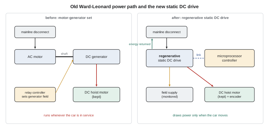
A controller modernization keeps the machine, so the drive must suit the motor already on it. Tillicum car 1 had a DC hoist motor powered by a Ward-Leonard motor-generator set: an AC motor turning a DC generator whose output voltage, varied by its field, set the hoist motor's speed. There were two ways forward. One was a static DC drive, an electronic converter that supplies the DC hoist motor's armature directly from the AC supply, with a separate field supply, replacing the motor-generator set but keeping the motor. The other was to replace the DC motor with an AC induction or permanent-magnet motor fitted to the existing gear and drive it with a variable-voltage, variable-frequency drive. The second gives a simpler, brushless motor, but means machining or replacing the motor mounting, coupling and brake drum arrangement on a 1962 worm gear, with more cost and outage time.
The survey had shown the DC motor in good condition, with high insulation resistance and a sound commutator, so the scope kept it and specified a regenerative static DC drive. Regenerative means the drive can run in all four quadrants: driving the motor in both directions and absorbing the energy when the motor is driven by the load, as when a full car goes down or an empty car goes up, and returning that energy to the supply instead of burning it in resistors. Older static DC drives used thyristors (silicon controlled rectifiers) in a pair of bridges; many newer ones use a transistor chopper fed from an active front end. Either way, the drive needs the motor's armature voltage and current, field voltage and current, base speed and the encoder or tachometer feedback that tells it how fast the motor is actually turning.
Sizing the drive
The drive must deliver the motor's current during acceleration, which is well above the steady running current, and its rating is checked against the motor and the job, not just copied from the motor nameplate. The power the motor must supply at constant speed depends on the out-of-balance load, the car speed and the efficiency of the machine. For a geared car with the counterweight balanced at a fraction of rated load, the worst case at steady speed is a full car going up, where the motor lifts the difference between the car with its load and the counterweight. Acceleration adds the torque needed to speed up the car, counterweight, ropes and rotating parts. Priya ran the numbers before accepting the drive the controller maker proposed.
# Drive and motor check for Tillicum car 1 (geared, 1:1 roping)
g = 9.81
rated = 1135            # rated load, kg
balance = 0.45            # counterweight balance as a fraction of rated load
v = 1.0                    # rated speed, m/s
eff = 0.62                # worm gear and sheave efficiency when driving (illustrative)
accel_factor = 1.5         # peak torque during acceleration relative to running (illustrative)
unbalanced = (1 - balance) * rated * g          # N, full car going up
p_shaft = unbalanced * v / eff / 1000           # kW at the motor shaft, steady speed
motor_kw, arm_v, arm_a = 15, 230, 75      # motor nameplate: power kW, armature V, armature A
i_run = arm_a * p_shaft / motor_kw              # running current, roughly proportional to load torque
i_peak = i_run * accel_factor
drive_a = 80                                  # drive continuous rating, A
drive_peak = drive_a * 1.5                      # drive short-time rating (150 % for 60 s, typical)
print(f"steady power full car up: {p_shaft:.1f} kW of a {motor_kw} kW motor ({100 * p_shaft / motor_kw:.0f} %)")
print(f"running armature current about {i_run:.0f} A, peak in acceleration about {i_peak:.0f} A")
print(f"drive {drive_a} A continuous, {drive_peak:.0f} A short time")
print("drive check:", "ok" if drive_a >= arm_a and drive_peak >= i_peak else "too small")steady power full car up: 9.9 kW of a 15 kW motor (66 %) running armature current about 49 A, peak in acceleration about 74 A drive 80 A continuous, 120 A short time drive check: ok
The motor worked at about two-thirds of its rating with a full car going up, and the drive's continuous rating covered the motor's full nameplate current with margin for acceleration peaks. Priya also checked the motor's field: the new field supply had to deliver the nameplate field current at the nameplate voltage, and it had to be monitored, because a DC motor that loses its field while the armature is energized can overspeed. The controller maker's drive included field loss detection; the pretest list in lesson 8 included a test of it.
The energy case
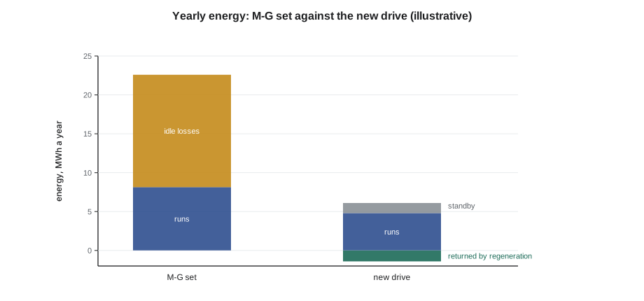
Energy savings are rarely the main reason for a modernization, but owners ask about them, and a Ward-Leonard car is the case where they are largest. The motor-generator set runs the whole time the car is in service, with losses in its AC motor, its generator and its windage and friction even when the car is parked; during runs, every conversion from AC to mechanical power to DC and back to mechanical power costs efficiency; and braking energy is lost in the generator and in resistors. A static drive draws only standby power between runs, converts power once, and with a regenerative drive returns some of the braking energy.
# Energy comparison: Ward-Leonard M-G set against a regenerative static DC drive (illustrative)
hours_on = 18 * 365            # hours a year the M-G set runs (car in service)
mg_idle_kw = 2.2                # M-G set losses when the car is parked, kW
runs_per_year = 260 * 365
kwh_per_run_motor = 0.06         # energy delivered to the hoist motor per average run, kWh
mg_eff = 0.70                      # M-G set conversion efficiency during runs
drive_eff = 0.92                   # static drive efficiency
drive_standby_kw = 0.15            # drive and controller standby
regen_return = 0.25                # share of motor energy returned to the supply by regeneration
price = 0.12                    # dollars per kWh, illustrative
mg = mg_idle_kw * hours_on + runs_per_year * kwh_per_run_motor / mg_eff
new = drive_standby_kw * 8760 + runs_per_year * kwh_per_run_motor * (1 / drive_eff - regen_return)
saved = mg - new
print(f"M-G set: {mg:,.0f} kWh a year; new drive: {new:,.0f} kWh a year")
print(f"saving {saved:,.0f} kWh a year ({100 * saved / mg:.0f} %), worth about {saved * price:,.0f} dollars a year")
part = 48000                      # dollars, the share of the job price for the drive alone
print(f"simple payback on the drive share alone: {part / (saved * price):.1f} years")M-G set: 22,588 kWh a year; new drive: 6,080 kWh a year saving 16,509 kWh a year (73 %), worth about 1,981 dollars a year simple payback on the drive share alone: 24.2 years
The calculation shows the pattern for Ward-Leonard cars: most of the old car's energy went into keeping the motor-generator set spinning, not into moving people, and the new drive cut the car's consumption by roughly three-quarters. Even so, the saving would pay back the drive alone only over about two decades at local power prices, which is why energy is usually a benefit of a modernization rather than its justification. Lesson 12 returns to the full life-cycle comparison the owner was shown.
Taking out the old controller
Removing a 1962 controller is careful work. The mainline is locked out and tested dead, then every circuit in the controller is confirmed dead, because old controllers often have circuits fed from elsewhere, such as hoistway lighting, an alarm bell transformer or a fire service circuit added in the 1980s. Old equipment can contain hazardous materials: asbestos in arc chutes, resistor insulation, wire insulation or the machine room floor tiles; mercury in old switches and relays; and oil-filled capacitors or transformers of an age that may contain polychlorinated biphenyls. Northcrest's procedure required a hazardous materials check before demolition, using the owner's building survey and labels on the equipment, and Tillicum's report listed asbestos in the old resistor panel's backing board, which was removed by an abatement contractor before Ray and Jonah touched the controller. Copper, steel and the motor-generator set went for recycling.
The old wiring diagrams were kept until the job was done. They are the only record of what the old controller connected to, and on a 1962 car with sixty years of changes, some of those connections were not on any drawing: Tamsin found a pair of wires from the controller to a lobby security desk that turned out to be a car-at-lobby signal installed decades earlier. The building manager wanted it kept, so it was added to the new controller as a spare output and noted on the new drawings.
Setting and wiring the new equipment
The new cabinets are set where the drawings put them, with the working clearance the electrical code requires in front of them, anchored, and bonded to the building's grounding system. The power wiring, from the mainline disconnect to the drive and from the drive to the motor armature and field, is sized and protected as the drawings show; armature cables are kept apart from control and encoder wiring to avoid interference. The encoder, which tells the drive the motor's speed and gives the controller a position reference, is mounted on the motor shaft extension with a flexible coupling so that the motor's end float does not damage it.
Hoistway and car wiring is the largest part of the work. The new controller communicates with the car over a serial link in the travelling cable, so far fewer conductors are needed than in a relay car, but the safety circuits, door locks and some emergency signals still run as individual wires, often in pairs for redundancy. Before ordering, Priya worked out the take-off from the hoistway drawing.
# Wiring take-off for Tillicum car 1 (lengths with allowance for routing and terminations)
travel = 30                 # m, bottom landing to top landing
mr_to_hoistway = 6             # m, controller to the top of the hoistway
stops = 9
tc_hitch = travel / 2             # travelling cable hitched at mid-hoistway
tc = tc_hitch + travel / 2 + 2 + mr_to_hoistway      # cable to the car at the bottom landing, plus loop and machine room run
landing_drop = 4             # m of cable from the riser to each landing's devices (interlock, hall fixture)
riser = travel + mr_to_hoistway + 3
interlock_runs = stops * landing_drop
allow = 1.10                      # 10 % for routing and terminations
print(f"travelling cable: {tc * allow:.0f} m (one length; order a reel with margin)")
print(f"hoistway riser cable: {riser * allow:.0f} m")
print(f"landing drops: {stops} x {landing_drop} = {interlock_runs * allow:.0f} m")
print(f"total hoistway wiring about {(riser + interlock_runs) * allow:.0f} m plus the travelling cable")travelling cable: 42 m (one length; order a reel with margin) hoistway riser cable: 43 m landing drops: 9 x 4 = 40 m total hoistway wiring about 82 m plus the travelling cable
First runs
The first time a new drive turns an old motor is the most dangerous moment of a modernization, because almost nothing has been proven: the motor might turn the wrong way, the encoder might read backwards, the brake might not lift fully, or a safety device might not be wired into the circuit it should be. The crew follows the controller maker's start-up procedure step by step. With the ropes on and the car and counterweight in their normal positions, the motor parameters are entered from the nameplate, the field current is set and checked, and the brake is lifted electrically with the motor not turning to confirm it releases and sets. The drive's motor tuning routine is run as the maker describes. The car is then moved on inspection operation at slow speed, first a few millimetres, with one person watching the machine and one at the controller ready to drop the mainline. The direction is checked against the push button, the encoder count against the movement, and the brake against the drive's commands.
Every jumper used during start-up is logged on the jumper board in the machine room: who placed it, where, why and when it was removed. At Tillicum, the controller's temporary run mode required two jumpers for the first day, one around the unfinished hoistway door circuit and one around the landing system inputs; both were on the board, tagged with Jonah's name, and both came off before the car moved on its own inspection operation. A jumper left in after start-up is one of the most common causes of serious accidents in the trade, which is why the pretests in lesson 8 begin with a count of every jumper on the board.
Worked problem
A motor that runs backwards
On the first inspection run after a DC drive change, the car moves down when the up button is pressed, slowly and smoothly. What is wrong and how is it fixed?
Show solution
- The motor's direction relative to the drive's command is reversed, either in the armature connections or in the drive's direction parameter.
- Stop immediately, set the brake and lock out the mainline.
- Check the encoder direction too: if the encoder and the motor are both reversed, the drive may run smoothly in the wrong direction; if only one is, it would usually fault or run away.
- Correct the direction as the maker's procedure describes, usually in the drive's settings, then confirm direction, encoder count and limit switch operation before going further.
Answer: Stop, then correct the direction in the way the maker specifies and re-prove the encoder and limits; never keep running a car whose direction is unproven.
Common mistakes
MistakeCopying the drive rating from the motor nameplate without checking peaks.
InsteadCheck running and acceleration current against the drive's continuous and short-time ratings.
MistakeIgnoring the DC field supply.
InsteadSet and monitor the field; a lost field can let a DC motor overspeed.
MistakeAssuming old circuits are dead because the mainline is off.
InsteadTest every circuit; old controllers have outside supplies.
MistakeStarting demolition without a hazardous materials check.
InsteadLook for asbestos, mercury and old oil-filled parts first.
MistakeLeaving start-up jumpers unrecorded.
InsteadLog every jumper on the board and remove them before inspection operation.
Summary and key terms
- A controller modernization keeps the machine, so the drive must suit the existing motor; a DC motor in good condition can stay with a static DC drive.
- Regenerative drives run in four quadrants and return braking energy to the supply.
- Size the drive from the out-of-balance load, speed, efficiency and acceleration, and check the field supply.
- Ward-Leonard cars waste most of their energy keeping the M-G set spinning; savings are real but rarely pay for the job alone.
- Remove old equipment only after proving every circuit dead and checking for hazardous materials.
- First runs follow the maker's start-up procedure: parameters, field, brake, direction, encoder, with every jumper logged.
- Static DC drive
- An electronic converter that supplies a DC hoist motor from the AC supply, replacing an M-G set.
- Regenerative drive
- A drive that returns braking energy to the supply instead of burning it in resistors.
- Four-quadrant operation
- Driving and braking in both directions of travel.
- Field supply
- The separate supply that magnetizes a DC motor’s field winding.
- Encoder
- A shaft-mounted sensor that reports motor speed and position to the drive and controller.
- Jumper board
- The log in the machine room recording every temporary jumper placed and removed.
Practice problems
Work each problem on paper first, then reveal the answer to check.
Why was the DC motor kept at Tillicum?
Show answer
The survey showed it sound, and an AC motor conversion would add cost and outage time.
What does a regenerative drive do with braking energy?
Show answer
Returns it to the supply.
When does a geared car need the most steady-speed power?
Show answer
With a full car going up, lifting the difference over the counterweight.
Why must the DC motor's field be monitored?
Show answer
Losing the field while the armature is energized can make the motor overspeed.
Why keep the old wiring diagrams until the job is done?
Show answer
They are the only record of what the old controller connected to.
Lesson quiz · 5 questions
Score 60% or more to complete this lesson.
Create a free account to save your progress, take quizzes and earn a certificate.