
ELV-310 · Lesson 5 of 12 · 20 min
Inputs, outputs, serial links and car-top stations
Larchmont Residences' single car had a complaint that sounded like a ghost: the car call button for the sixth floor sometimes lit by itself at night, and the car would travel empty to six, open its doors and wait. The building manager suspected a prank. Priya suspected a wire. On the controller's display she watched the input for the sixth-floor car call while Tamsin ran the car on inspection from the car top, and each time the car passed the fourth floor the input flickered on for a few milliseconds. The car operating panel's wiring had been pinched behind a panel during the cab finishing, and the travelling cable's movement at that point in the hoistway was enough to touch a bared conductor to the supply. The ghost was an input. This lesson covers how a controller reads its inputs, drives its outputs, and talks to the car and hall fixtures over serial links.
Inputs
An input is any signal the controller reads: a switch, a sensor, a push button, a relay contact. On modern controllers most inputs run at 24 V DC. A switch connects the input terminal to the supply, and the input board sees the voltage and reports the input as on. Most input boards show each input's state with a small lamp, and the controller's display or service tool can show it as well, which makes the input the first place to look when a car does not respond to a device.
Inputs come in two wiring styles, and confusing them is a common mistake when replacing a sensor. A sourcing device supplies the voltage to the input, so the input is on when the device connects the input to positive; a sinking device connects the input to the negative or common side. Electronic sensors such as proximity switches and photo-eyes are labelled PNP for sourcing and NPN for sinking. A PNP sensor on an input board built for sinking inputs will either never turn the input on or always leave it on, depending on the board. Before replacing any sensor, the mechanic checks the print for the input type and matches the part.
Inputs are also normally open or normally closed. A car call button is normally open: pressing it turns the input on. A door limit or a safety device is normally closed: the input is on while everything is in order, and it turns off when the device operates or the wire breaks. Using normally closed inputs for anything that matters to safety means a broken wire is read as the device operating, which is the safe interpretation. Priya has a rule for reading an input lamp: a lamp that is off for a normally closed device is a device operated or a broken wire, and you find out which before you do anything else.
Outputs
An output is any signal the controller drives: a relay coil, a contactor, a lamp, a buzzer, the door operator's open and close commands. Output boards switch either through small relays, whose contacts can switch AC or DC loads up to a few amperes, or through transistors, which switch DC loads quickly and silently but can be damaged by a short circuit or by the voltage spike from a coil without a suppression diode. ELV-210's lesson on relays covered why every DC coil switched by a transistor needs a diode across it. Larger loads, such as the motor and brake, are switched by contactors whose coils are driven by outputs.
Outputs fail in two ways: off, where the output never turns on, and stuck on, where a transistor has shorted or relay contacts have welded. A stuck-on output to a safety-related device is why safety outputs are duplicated and checked, as Lesson 2 described. For ordinary outputs, such as a hall lantern or a car call acknowledgement lamp, a stuck-on output is an annoyance rather than a hazard, but it can still cost an hour if the mechanic looks for a stuck button instead of a failed output.
From point-to-point wiring to serial links
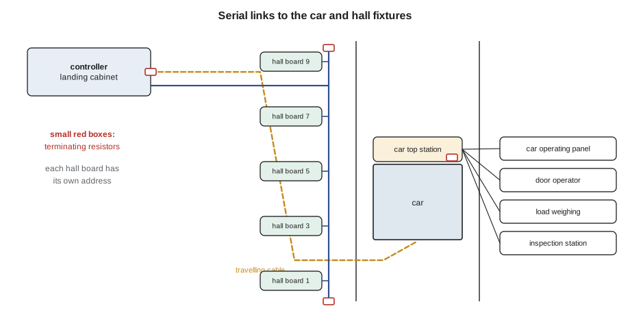
On Tillicum car 1, every button, lamp, switch and sensor in the car and hall has its own pair of wires to the machine room: the car's travelling cable has more than 80 conductors and the hoistway wiring more than 200. Each call button needs a wire to the controller for the call and another for its lamp. A modern controller replaces most of those wires with serial links. A board on the car top, often called the car top station or car top board, reads every input on the car and drives every output on the car, and sends the information to the controller over two or four conductors in the travelling cable. A board in the car operating panel does the same for the buttons and display, and boards in each hall fixture do it for the hall buttons and lanterns, all on a shared pair of wires running the height of the hoistway.
The serial link carries messages: short groups of bits that say which board is speaking and what it reports. Elevator controllers use several kinds of link. CAN, a network originally developed for vehicles, is common between the controller, the car top and the drive; RS-485 links are common for hall fixtures; and some controllers use Ethernet between the controller, the group and remote monitoring. All of them use a twisted pair of conductors, often shielded, and most need a terminating resistor at each end of the line to stop signals reflecting back from the ends.
Addresses, termination and how links fail
Every board on a shared line has an address so the controller knows who is speaking. Hall fixture boards are usually addressed by floor and by position, for example floor 6 up and down buttons and floor 6 lantern, set by small switches or by a learning procedure during installation. Two boards with the same address will fight, and the controller will see garbled messages from both. A replaced hall board left at its factory address is one of the most common causes of a hall fixture fault after a repair.
Serial links fail in a few familiar ways. A missing or extra terminating resistor makes the signal ring and messages corrupt, often only on long lines or at high data rates. A broken shield or a shield grounded at the wrong end lets drive noise in. A pinched or chafed conductor in the travelling cable can drop the link only at certain car positions, as the cable flexes. A water-damaged hall fixture can pull the whole line down, so that every hall call in the building stops working. The controller usually logs communication errors by board address and counts retries, which turns a vague complaint into a list of suspects.
# Check termination on a serial line by measuring across the pair with power off
nominal = 120.0          # ohms, each terminating resistor on this kind of line
readings = {"correct, two terminators": 60.4, "one terminator missing": 119.0,
            "three terminators (extra on a replaced board)": 40.1, "pair shorted": 0.6}
for case, r in readings.items():
    n = nominal / r if r > 1 else float("inf")
    if r < 5:
        verdict = "short circuit on the pair"
    elif abs(n - 2) < 0.2:
        verdict = "two terminators, as required"
    else:
        verdict = f"looks like {n:.0f} terminator(s) in parallel"
print(f"{case:<46} {r:6.1f} ohm -> {verdict}")correct, two terminators 60.4 ohm -> two terminators, as required one terminator missing 119.0 ohm -> looks like 1 terminator(s) in parallel three terminators (extra on a replaced board) 40.1 ohm -> looks like 3 terminator(s) in parallel pair shorted 0.6 ohm -> short circuit on the pair
With power off, two 120 Ω resistors in parallel read about 60 Ω across the pair. One reads about 120 Ω; three read about 40 Ω. The values depend on the type of link, so the mechanic checks the maker's figure, but the method is the same for any terminated line.
Checking messages: checksums
A message on a serial link can be damaged by noise between the sender and the receiver. To catch this, the sender adds a check value calculated from the message's contents, and the receiver calculates the same value from what it received and compares. If they disagree, the message is thrown away and usually sent again. The simplest check is a sum of the bytes; serial links in vehicles and elevators use stronger checks called cyclic redundancy checks, or CRCs, which catch almost every kind of damage. A mechanic never calculates a CRC on the job, but the idea explains why a noisy link shows up as retries and error counts rather than wrong calls, and why a link that is getting worse shows a rising error count long before it fails.
# A simple checksum and a CRC on a hall call message
msg = [0x06, 0x01, 0x01]      # address of the floor 6 board, message type: call, button: up

def checksum(data):
    return sum(data) % 256

def crc8(data, poly=0x07):
    crc = 0
    for byte in data:
        crc ^= byte
        for _ in range(8):
            crc = ((crc << 1) ^ poly) & 0xFF if crc & 0x80 else (crc << 1) & 0xFF
    return crc

sent = msg + [crc8(msg)]
print("sent bytes:", [hex(b) for b in sent], " sum check:", hex(checksum(msg)))
for damaged in ([0x06, 0x01, 0x03], [0x07, 0x01, 0x00]):
    ok_sum = checksum(damaged) == checksum(msg)
    ok_crc = crc8(damaged) == sent[-1]
print("received", [hex(b) for b in damaged], " sum passes:", ok_sum, " CRC passes:", ok_crc)sent bytes: ['0x6', '0x1', '0x1', '0x6f'] sum check: 0x8 received ['0x6', '0x1', '0x3'] sum passes: False CRC passes: False received ['0x7', '0x1', '0x0'] sum passes: True CRC passes: False
The second damaged message changes two bytes in ways that cancel out in a simple sum, so the sum check passes a wrong message; the CRC catches it. That is why serious links use CRCs.
The car top station
The car top station is where the controls mechanic spends much of their time. On Quayside car 2 it is a steel box on the crosshead with the inspection station on its face: the stop switch, the inspection and normal switch, the run button and the up and down buttons, a light and a socket. Inside is the car top board, with terminals for the door operator, the car door contact, the levelling and door zone sensors, the load weighing device, the car lighting and fan, the emergency exit contact and the car operating panel link, and a connector for the travelling cable. On a new car, the car top board's lamps and the controller's display between them show the state of every device on the car.
Because so much depends on it, the car top station is also a common place for faults. Water from a car wash or a leaking roof finds its way to car tops; the travelling cable connector is flexed on every run; door operator wiring is moved during every door adjustment. Priya's habit when she arrives on a car top for any reason is to look at the board's lamps and the connectors before she starts, and to note anything unusual in the log, so a fault that appears later has a starting point.
Inspection operation from the car top uses the inspection station's inputs, and the code sets rules for them. The run and direction buttons are constant pressure, so the car stops as soon as they are released. The inspection switch, when on, takes the car off normal service and limits it to inspection speed. Most cars require the run button to be pressed together with a direction button, so a single accidental press cannot move the car. On a microprocessor car, these inputs go to the controller and also, on many cars, to the safety board, which can stop the car if they disagree.
Load weighing
Many cars have a load weighing device: strain gauges or a displacement sensor under the platform, on the crosshead or on the rope hitches, read by the car top board. The controller uses the load for three things. It tells the drive the load before the brake lifts, so pre-torque matches the load and the car does not jump. It stops the car from leaving a floor when it is overloaded, with a buzzer and a message. And it tells the group how full the car is, so a full car can bypass hall calls. A load weighing device that drifts can make starts rough or make the group bypass calls with a half-empty car, so its calibration is checked with test weights during periodic tests.
# Calibrate a load weighing sensor with two test loads, then read a load
empty_reading, empty_load = 1210, 0          # sensor counts with the car empty
test_reading, test_load = 3290, 1000          # counts with test weights in the car
slope = (test_load - empty_load) / (test_reading - empty_reading)
for counts in (1210, 2250, 3750, 4100):
    load = empty_load + slope * (counts - empty_reading)
    share = load / 1600 * 100
    state = "overload, car held at floor" if share > 110 else ("full, bypass hall calls" if share > 80 else "normal")
print(f"{counts} counts = {load:6,.0f} kg ({share:5.1f} % of rated) {state}")1210 counts = 0 kg ( 0.0 % of rated) normal 2250 counts = 500 kg ( 31.2 % of rated) normal 3750 counts = 1,221 kg ( 76.3 % of rated) normal 4100 counts = 1,389 kg ( 86.8 % of rated) full, bypass hall calls
Common mistakes
MistakeFitting an NPN sensor where the print calls for PNP, or the reverse.
InsteadCheck the input type on the print and match the sensor's output type.
MistakeReading an off lamp on a normally closed input as a failed board.
InsteadIt means the device has operated or the wire is broken; check the device and wiring first.
MistakeLeaving a replaced hall board at its factory address.
InsteadSet its address to match the floor and position before connecting it to the line.
MistakeAdding a terminating resistor on a new board in the middle of a line.
InsteadOnly the two ends of the line are terminated; check across the pair with power off.
MistakeIgnoring a rising communication error count because the car still works.
InsteadA rising count warns of a chafed conductor, a bad shield or a failing board before the link fails.
Summary and key terms
- Inputs are read at 24 V DC on most modern controllers; know whether each is sourcing or sinking and normally open or normally closed.
- Safety-related inputs are normally closed so a broken wire reads as the device operating.
- Outputs switch through relays, transistors or contactors and can fail off or stuck on.
- Serial links replace point-to-point wiring between the controller, the car top, the car operating panel and the hall fixtures.
- Links need correct addresses and a terminating resistor at each end, and they show trouble as rising error counts.
- Checksums and CRCs let receivers reject damaged messages.
- The car top station and load weighing device are central to inspection operation, starting and dispatching.
- Input
- A signal the controller reads, such as a switch, sensor or button.
- Output
- A signal the controller drives, such as a relay coil, contactor, lamp or buzzer.
- Sourcing and sinking
- Whether a device supplies the positive voltage to an input or connects it to common; PNP and NPN sensors respectively.
- Serial link
- A connection that carries many signals as messages over a few conductors.
- Terminating resistor
- A resistor at each end of a serial line that stops signals reflecting from the ends.
- CRC
- Cyclic redundancy check: a check value calculated from a message that lets the receiver detect damage.
- Car top station
- The box on the car top with the inspection controls and the board that connects the car's devices to the controller.
Practice problems
Work each problem on paper first, then reveal the answer to check.
A normally closed door limit input lamp is off with the doors closed. Name two possible causes.
Show answer
The limit switch is open or out of adjustment, or the wire or connector is broken.
What resistance do you expect across a properly terminated serial pair with two 120 Ω terminators, power off?
Show answer
About 60 Ω.
After a hall fixture board is replaced, every call at that floor and another floor misbehaves. What is the first thing to check?
Show answer
The new board's address; it may duplicate another board's address.
Why are car call buttons normally open but safety devices normally closed?
Show answer
A broken wire must read as the safe condition: no call for a button, device operated for a safety device.
Give two uses of the load weighing signal.
Show answer
Any two of: setting pre-torque before the brake lifts, preventing an overloaded car from leaving, telling the group a car is full so it bypasses hall calls.
Lesson quiz · 5 questions
Score 60% or more to complete this lesson.
Create a free account to save your progress, take quizzes and earn a certificate.