
ELV-310 · Lesson 3 of 12 · 22 min
Reading relay controller prints and sequences
Tillicum car 1's controller came with a set of prints that had been folded, taped, written on and coffee-stained for sixty years. Ray kept the originals in a steel tube in the machine room and worked from a scanned copy in a plastic sleeve, with the mechanics' changes marked in red. "The print is the controller," he told Tamsin. "If the wiring and the print disagree, you find out why before you touch anything." Priya used the same prints to teach Tamsin the sequence of a run: the order in which the relays pick up and drop out from the moment a call is registered to the moment the doors open at the next floor. Once a mechanic knows the sequence, a relay that fails to pick up at its step points straight at the fault.
How relay prints are organized
Most relay controller prints share a layout that ELV-210's lesson on wiring diagrams introduced. The power circuits come first: the main line, the motor-generator set or hoist motor contactors, the brake and the door operator. The control circuits follow as ladder rungs, usually in the order of the sequence: safety circuit, door circuits, call registration, direction, starting and speed control, levelling and stopping. Each rung has a line number in the margin. Beside each coil, a cross-reference column lists the line numbers where that coil's contacts appear, with a mark showing whether each contact is normally open or normally closed. A contact on line 47 marked U, with a cross-reference under the U coil showing 47 among its contacts, tells the reader that the up direction relay controls something on line 47.
Old prints use symbols that differ from current standards, and different makers drew the same thing differently. Tillicum's prints show relay contacts as two short parallel lines, with a diagonal for normally closed, much like current practice, but they show the floor selector as a long rectangle with brushes and segments, and the generator field as a zigzag resistor with taps. Ray had added a legend sheet in the sleeve, copied from the manufacturer's old manual, and Tamsin added her own notes as she learned.
| Name | Device | What it does in the sequence |
|---|---|---|
| SAF | safety relay | picks up when the safety circuit is made; its contacts enable everything else |
| DC / DO | door close and door open relays | drive the door operator motor |
| GS / DL | gate switch and door lock relays | prove the car door is closed and the hoistway doors are locked |
| U / D | direction switches | select up or down by switching the generator field; picked by the selector |
| BK | brake relay | lifts the brake when a direction switch is in |
| H | high speed relay | cuts out field resistance so the generator, and so the car, runs at full speed |
| SD | slowdown relay | dropped by the selector at the slowdown point ahead of a stopping floor |
| LU / LD | levelling relays | picked by the car top levelling switches inside the levelling zone |
| RUN | run relay | holds in while the car is moving; its drop-out starts the door open |
The sequence of a run
Priya had Tamsin stand in front of the open controller while Ray ran the car from the lobby to the seventh floor and back, and name each relay as it pulled in. On a relay controller every step makes a sound, and an experienced mechanic can hear a fault as clearly as see it. The sequence for an up run from the lobby, with the doors open and a car call registered for floor 7, goes like this.
- Call registered. The car call relay for floor 7 seals itself in through a contact that opens when the selector reaches floor 7 with the car travelling up.
- Direction picked. The selector's brushes see a call above the car's position, and the up preference relay picks up.
- Doors close. With a direction picked and the door hold time expired, the door close relay DC picks up and the door operator closes the doors.
- Locks proved. The gate switch and the hoistway door lock close; GS and DL pick up. The door close relay drops when the doors reach their closed limit.
- Start. With SAF, GS and DL in and a preference set, the up direction switch U picks up. It switches the generator field in the up direction and, through a contact, picks the brake relay BK, which lifts the brake. RUN picks up and holds.
- Accelerate. After a short time delay, the high speed relay H picks up and cuts out field resistance in steps; the generator voltage rises and the car accelerates to full speed.
- Slowdown. When the selector reaches the slowdown point for floor 7, it drops SD; SD drops H, the field resistance is reinserted, and the car slows to levelling speed.
- Level. As the car enters the levelling zone, the car top levelling switch picks up LU, which keeps the car moving slowly until the switch drops at the exact floor level.
- Stop. U drops, the generator field is opened, BK drops and the brake sets. RUN drops, and its drop-out starts the door open relay DO. The call for floor 7 is cancelled.
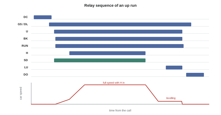
Each step depends on the one before it. U cannot pick unless SAF, GS and DL are in. H cannot pick unless U and RUN are in. DO cannot pick while RUN is in. A car that closes its doors and then sits without moving, with the doors closed and the call lit, has stopped at the step where the locks are proved or the direction switch picks; a car that starts and runs only at slow speed has stopped at the step where H picks. Priya's first question on any relay car complaint is: at which step does the sequence stop?
Following the sequence as a state machine
A microprocessor controller follows the same sequence, but in software. The program is written as a state machine: the car is always in exactly one state, such as idle, closing doors, starting, running, slowing, levelling, stopped or opening doors, and it moves to the next state only when the conditions for that transition are met. Writing the relay sequence as a state machine is a good way to understand both kinds of controller, because each relay step becomes one transition with its conditions.
# A run cycle written as a state machine; each step needs its conditions
inputs = {"call_ahead": True, "safety": True, "car_door_closed": False,
          "locks_made": False, "at_slowdown": False, "level": False}

def step(state, i):
    if state == "doors open" and i["call_ahead"]:
        return "closing doors"
    if state == "closing doors" and i["car_door_closed"] and i["locks_made"]:
        return "starting"
    if state == "starting" and i["safety"]:
        return "running"                 # direction switch in, brake lifted
    if state == "running" and i["at_slowdown"]:
        return "slowing"                 # high speed dropped
    if state == "slowing" and i["level"]:
        return "stopped"                 # direction switch out, brake set
    if state == "stopped":
        return "opening doors"
    return state

events = [{}, {"car_door_closed": True}, {"locks_made": True}, {}, {},
          {"at_slowdown": True}, {}, {"level": True}, {}]
state = "doors open"
for n, e in enumerate(events, 1):
    inputs.update(e)
    new = step(state, inputs)
    note = "" if new != state else "   (waiting)"
    print(f"{n}: {state:<14} -> {new}{note}")
state = new1: doors open -> closing doors 2: closing doors -> closing doors (waiting) 3: closing doors -> starting 4: starting -> running 5: running -> running (waiting) 6: running -> slowing 7: slowing -> slowing (waiting) 8: slowing -> stopped 9: stopped -> opening doors
The printout shows the controller waiting at step 2, because the car door has closed but the hoistway door lock has not made. On Tillicum car 1, a mechanic would see the same thing as DC dropping, GS in and DL not picking. On Quayside car 2, the service tool would show the state as closing doors and the input for the lock circuit off. The language is different and the logic is the same.
Timers and adjustments
Relay controllers adjust their behaviour with timers and resistors. Tillicum car 1's door hold time is set by a dashpot timer, a relay whose armature is slowed by a small air or oil cylinder with an adjustable bleed; its acceleration is set by the timing of relays that cut out generator field resistance in steps; its slowdown distance is set by the position of the slowdown contacts on the selector. Each of these settings drifts as parts wear and oil thickens. A car that has started to overshoot floors in cold weather may have a slowdown relay or dashpot that is slower than it used to be, or a selector whose contacts have worn.
Priya keeps a sequence record for each relay car: a table of the relays in order and the time each picks up after the start of a run, measured with a meter's min/max function, a stopwatch, or on a recent visit a small data logger clipped to coil terminals. When a car changes, she compares the new times to the record. At Tillicum, the delay between U and H had grown from 0.9 s in her record to 1.6 s, which explained the complaint that the car had become sluggish leaving floors; the time delay relay's adjustment had loosened and been knocked.
# Compare relay pick-up times in a run with the sequence record
record = {"GS/DL": 0.00, "U": 0.25, "BK": 0.30, "H": 1.15, "SD": 9.80, "LU": 11.60}
today = {"GS/DL": 0.00, "U": 0.26, "BK": 0.32, "H": 1.86, "SD": 10.50, "LU": 12.30}
limit = 0.30   # seconds of change worth investigating
prev_rec, prev_now = 0.0, 0.0
for relay in record:
    gap_rec = record[relay] - prev_rec
    gap_now = today[relay] - prev_now
    flag = "  <-- changed" if abs(gap_now - gap_rec) > limit else ""
    print(f"{relay:<6} step {gap_rec:4.2f} s in record, {gap_now:4.2f} s today{flag}")
prev_rec, prev_now = record[relay], today[relay]GS/DL step 0.00 s in record, 0.00 s today U step 0.25 s in record, 0.26 s today BK step 0.05 s in record, 0.06 s today H step 0.85 s in record, 1.54 s today <-- changed SD step 8.65 s in record, 8.64 s today LU step 1.80 s in record, 1.80 s today
Comparing the time between steps, rather than the time from the start, isolates the change. Only the step to H has changed; everything after it has moved later by the same amount but its own step is unchanged. The fault is in the H timing, not in the selector or the levelling.
When the print and the wiring disagree
On a sixty-year-old controller, the print is rarely perfect. Mechanics have added relays for code upgrades, moved wires around failed contacts, removed features nobody used, and not always marked the print. Ray's rules are simple. Before changing anything, compare the wiring at the point of interest to the print. If they disagree, trace the wiring until you know what it actually does, mark the print in red with the date and your initials, and tell the supervisor. Never assume a wire that does not appear on the print is unused, and never remove one without proving where both ends go. On Tillicum car 1, Tamsin found a relay in the corner of the cabinet that was not on any print; Ray traced it to a 1998 upgrade that added a firefighters' recall input, and the drawings for that upgrade were in a separate folder in the building manager's office.
Microprocessor controllers have their own version of this problem. The prints show the wiring between boards and devices, and the job-specific parameters, such as floor heights, door times and special operations, are stored in the controller's memory. Northcrest saves a copy of the parameters for every microprocessor car after each adjustment, so that a board replacement or a mechanic's change can be compared against the last known good set.
Worked problem
At which step does the sequence stop?
Tillicum car 1 has a complaint: with a call registered, the doors close fully, the car sits for a few seconds, and then the doors reopen and the call stays lit. In the controller, Tamsin sees DC pick up and drop out and GS pick up, but DL never picks. Where should she look?
Show solution
- The sequence reaches the doors-closed step, so the door operator and the car door contact are working.
- DL not picking means the hoistway door lock circuit is open, even though the car door is closed.
- The controller's door reopening after a delay is its response to locks not made within the allowed time.
- The fault is in the hoistway door interlock circuit at the floor where the car is standing, or in its wiring; she should check the interlock at that landing first, on inspection operation with the doors closed.
Answer: The sequence stops at the lock-proving step; the hoistway door interlock at that landing is the first suspect.
Common mistakes
MistakeStarting a relay car fault by replacing relays at random.
InsteadFind the step at which the sequence stops; that points to the circuit to test.
MistakeMeasuring times from the start of the run to compare with the record.
InsteadCompare the time between steps, so one slow step does not make every later step look slow.
MistakeTrusting an old print without checking the wiring.
InsteadCompare wiring and print at the point of work; mark any difference in red and report it.
MistakeRemoving an unknown relay or wire because it is not on the print.
InsteadTrace both ends and find what it does; it may be an unrecorded code upgrade.
MistakeThinking microprocessor controllers follow a different sequence.
InsteadThey follow the same steps in software as a state machine; only the tools for watching them differ.
Summary and key terms
- Relay prints show power circuits, then control rungs in sequence order, with line numbers and cross-references for every coil's contacts.
- A run follows a fixed sequence: call, direction, door close, locks proved, direction switch and brake, high speed, slowdown, levelling, stop, door open.
- Each step depends on the previous ones; the step at which the sequence stops points to the fault.
- Microprocessor controllers run the same sequence as a state machine.
- Relay timings drift; compare the time between steps with a sequence record.
- When print and wiring disagree, trace the wiring, mark the print and report it.
- Cross-reference
- The column beside a coil on a print listing the line numbers where its contacts appear.
- Sequence of operation
- The order in which a controller's relays or states change during a run.
- Direction switch
- A contactor or relay that selects up or down travel; on a Ward-Leonard car it switches the generator field.
- Dashpot timer
- A time-delay relay whose movement is slowed by an air or oil cylinder with an adjustable bleed.
- Levelling zone
- The short distance above and below a floor in which levelling switches or sensors bring the car to an exact stop.
- State machine
- A program in which the system is always in one defined state and moves to the next only when its conditions are met.
- Sequence record
- A table of the relays or states in a run and the time each step takes, kept to compare with later runs.
Practice problems
Work each problem on paper first, then reveal the answer to check.
A relay car closes its doors, proves its locks and lifts its brake, but runs only at slow speed. At which step has the sequence stopped?
Show answer
At the high speed step: H is not picking, or its time delay or contacts have failed.
Why must DO not pick up while RUN is in?
Show answer
So the doors cannot open while the car is moving.
What does a mark of 47 in the cross-reference under coil U tell you?
Show answer
That a contact of the up direction relay appears on line 47 of the print.
In a sequence record, the time to H rose by 0.7 s and every later time rose by about 0.7 s. Which step changed?
Show answer
Only the step to H; the later steps moved with it.
Tamsin finds a wire on a terminal that does not appear on the print. What should she do?
Show answer
Trace both ends to find what it does, mark the print with the finding, date and initials, and tell her supervisor before changing anything.
Lesson quiz · 5 questions
Score 60% or more to complete this lesson.
Create a free account to save your progress, take quizzes and earn a certificate.