
ELV-210 · Lesson 7 of 12 · 21 min
Relays, contactors and control devices
Before microprocessors, every decision an elevator made was made by relays: electrically operated switches whose contacts open and close when a coil is energized. The Tillicum Building's cars still run on a relay controller from the 1960s, a cabinet of several dozen relays, contactors and timers clicking in sequence each time a car starts and stops. Modern controllers have replaced most of the logic with software, but they still use relays and contactors at the points where control meets power: the safety relays, the brake and motor contactors, and the outputs that drive the door operator and signals. Tamsin will spend her career reading, testing and replacing these devices, and this lesson explains how they work.
How a relay works
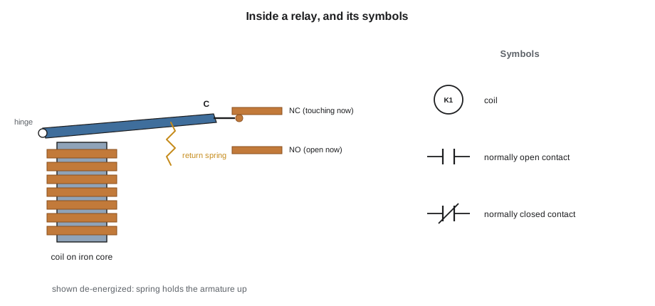
A relay has two parts that are electrically separate. The coil is an electromagnet wound on an iron core. The contacts are switches mounted on a movable armature. When current flows in the coil, the core pulls the armature in against a spring, and the contacts change state. When the coil is de-energized, the spring returns the armature and the contacts go back to their normal state. The normal state is the state with the coil de-energized, and it is the state shown on wiring diagrams.
A normally open contact, often marked NO or drawn as two parallel lines, is open when the coil is off and closes when the coil is energized. A normally closed contact, marked NC or drawn with a diagonal line, is closed when the coil is off and opens when it is energized. Many relays have changeover contacts, also called form C, with a common terminal that connects to one side when the coil is off and the other side when it is on. Because the coil circuit and the contact circuit are separate, a small current in a 24 V or 120 V coil can switch a different circuit entirely, at another voltage or of much greater current.
Pickup, dropout and coil ratings
A relay coil is designed for a nominal voltage, but it does not need exactly that voltage to operate. The pickup voltage is the lowest voltage at which the armature reliably pulls in, typically around 75 to 85 percent of nominal. The dropout voltage is the voltage below which a pulled-in relay releases, much lower, often 10 to 30 percent of nominal, because the closed magnetic circuit needs much less current to hold it. That gap between pickup and dropout gives a relay a useful stability: once operated, it does not chatter as the voltage wanders.
The gap also explains two faults. A relay fed with too little voltage may not pick up at all, or may pick up on one start and fail on the next, which is how a resistive contact in the safety string or a sagging control transformer shows itself. A relay that fails to drop out when its coil circuit is opened usually has a leakage path keeping a little current in its coil, a residual magnetism problem, or contacts that have welded on another relay feeding it.
Contact ratings
A relay's contacts are rated separately from its coil, for a maximum voltage and current, and separately for AC and DC and for resistive and inductive loads. Breaking an inductive DC circuit is the hardest duty. When the contacts open, the coil's stored magnetic energy tries to keep the current flowing, and an arc forms across the opening gap. On AC, the arc goes out naturally when the current passes through zero, a hundred and twenty times a second. On DC there is no zero, and the arc can persist and burn the contacts. A relay rated for ten amperes at 250 V AC may be rated for only a fraction of an ampere at 125 V DC with an inductive load. Replacing a relay with one that has the same coil and the same pin layout but a lower DC contact rating is a classic cause of repeat failures on brake circuits.
Suppressing coil switching
When a DC coil is switched off, its current collapses quickly and its inductance produces a voltage spike that can be many times the supply voltage. The induced voltage is the inductance times the rate of change of current.
The spike arcs across the contacts that switched it, interferes with electronics nearby and can damage the output transistor of a controller board. It is suppressed by a component connected across the coil: a diode on DC coils, an RC network or a varistor on AC coils. A diode across a DC coil is connected so that it does not conduct normally, and when the coil is switched off, the coil current circulates through the diode and dies away slowly. That slows the release of the relay or brake, which matters on a brake, so brake coils often use a diode in series with a resistor or a varistor to release faster. A missing or failed suppressor is a common cause of controller board output failures, and a suppressor fitted the wrong way round on a DC coil is a dead short that blows the fuse the first time the coil is energized.
# Switching off a DC brake coil: spike without suppression, release time with a diode
L = 1.8              # coil inductance, H
R = 64.0             # coil resistance, ohms
v = 100.0            # supply, V
i0 = v / R           # current at switch-off, A
t_open = 50e-6       # time for an unsuppressed contact to interrupt the current, s
print(f"coil current {i0:.2f} A, stored energy {0.5 * L * i0 ** 2:.2f} J")
print(f"unsuppressed spike about {L * i0 / t_open:,.0f} V")
import math
tau_d = L / (R + 1.0)            # diode only: current circulates through the coil
tau_dr = L / (R + 150.0)         # diode plus 150-ohm resistor
hold_frac = 0.25                 # brake releases when current falls to 25 % of start
for name, tau, vmax in (("diode", tau_d, 0.7), ("diode + 150 ohm", tau_dr, 0.7 + 150 * i0)):
    t = tau * math.log(1 / hold_frac)
print(f"{name:<16} time to release {1000 * t:5.1f} ms, peak voltage {vmax:5.0f} V")coil current 1.56 A, stored energy 2.20 J unsuppressed spike about 56,250 V diode time to release 38.4 ms, peak voltage 1 V diode + 150 ohm time to release 11.7 ms, peak voltage 235 V
The diode alone limits the spike to less than a volt but makes the brake take tens of milliseconds to set. Adding a resistor in series with the diode speeds the release at the cost of a higher, but still controlled, voltage. The brake manufacturer specifies the arrangement, and a mechanic replacing a brake rectifier or suppressor fits exactly what is specified.
Holding circuits and interlocks
Relays can remember. If a normally open contact of a relay is wired in parallel with the push button that energizes its coil, then once the button is pressed and the relay picks up, its own contact keeps its coil energized after the button is released. This is a holding circuit, also called a seal-in or latch. The relay stays in until something in series with the combination opens, such as a normally closed reset contact. A car call circuit on a relay controller works this way: the call button picks up a call relay, the relay holds itself in, and when the car stops at that floor a contact of the floor relay breaks the holding circuit and cancels the call.
An interlock prevents two relays from being energized together. The up and down direction contactors are the essential example: if both closed at once on an across-the-line motor, they would short two phases of the supply. Each contactor's coil is fed through a normally closed contact of the other, so that the down contactor cannot pick up while the up contactor is in, and the two are often mechanically interlocked as well, with a lever that physically prevents both armatures from closing.
| Device | What it does | Where an elevator uses it |
|---|---|---|
| General-purpose relay | Low-current logic switching | Call registration, direction logic and signals on relay controllers |
| Contactor | Switches motor and brake power, with arc chutes | Main line contactors, brake contactor, pump motor starter |
| Safety relay with guided contacts | Contacts mechanically linked so a welded contact is detectable | Safety circuit and door lock monitoring |
| Time-delay relay | Operates after a set delay on energizing or de-energizing | Door hold times, star-delta transfer, brake drop timing on older equipment |
| Overload relay | Trips on sustained overcurrent | Hydraulic pump motor starters |
| Solid-state relay | Switches with semiconductors, no moving contacts | Signals, fans, some door operators |
Contactors and guided contacts
A contactor is a heavy-duty relay built to switch motor and brake currents. It has larger contacts, stronger springs and arc chutes that stretch and cool the arc when the contacts open under load. The main line contactors in an elevator controller disconnect the motor or drive output each time the car stops. Elevator codes require that the hoist motor and brake be controlled so that a single failure, such as a welded contactor contact, cannot leave the car able to run with the brake released after a stop. Controllers do this with two contactors in series, each switching all of the motor's supply, and they monitor both: after every stop, the controller checks that each contactor has actually dropped out, and if one has not, it prevents the next start.
That monitoring relies on guided or forcibly guided contacts. In a relay with guided contacts, the normally open and normally closed contacts are linked mechanically so that they can never both be closed. If a normally open contact welds shut, the normally closed contacts on the same relay stay open even when the coil is de-energized. The controller reads the normally closed contact as its proof that the relay has released. A failed check is shown as a fault such as a contactor or safety relay proof failure, and the car is shut down until a mechanic finds the welded or sticking device.
Time-delay relays
A time-delay relay operates its contacts after a delay. An on-delay relay changes its contacts a set time after its coil is energized and returns them immediately when the coil is de-energized. An off-delay relay changes its contacts immediately when energized and holds them for a set time after de-energizing. Modern timers are electronic, but on older relay controllers the delay was produced by a capacitor charging through a resistor, by a dashpot, or by a copper slug on the relay core that slowed the collapse of the magnetic field. The capacitor version is easy to calculate: the voltage on the capacitor rises toward the supply with a time constant equal to resistance times capacitance, and the relay picks up when the voltage reaches its pickup level.
# An RC time delay on an old Tillicum door-hold relay (illustrative values)
import math
vs = 125.0            # DC supply to the timing circuit, V
pickup = 0.80 * vs    # relay picks up at 80 % of the supply
C = 470e-6            # F
for R in (4700, 6800, 10000):
    tau = R * C
    t = -tau * math.log(1 - pickup / vs)
print(f"R = {R:5d} ohm: time constant {tau:5.2f} s, relay picks up after {t:4.1f} s")R = 4700 ohm: time constant 2.21 s, relay picks up after 3.6 s R = 6800 ohm: time constant 3.20 s, relay picks up after 5.1 s R = 10000 ohm: time constant 4.70 s, relay picks up after 7.6 s
Because the delay depends on the capacitor, an old timing capacitor that has lost capacitance shortens the delay, and the doors on a relay car start closing too soon. Ray's approach on a short door time is to measure the delay with a stopwatch, compare it with the adjustment on the wiring diagram, and test the capacitor with a meter that has a capacitance function before turning the adjusting resistor.
Sensors and switches
The inputs to relays and controller boards come from switches and sensors. Limit switches are operated by a cam on the car or by the car striking a lever. Proximity sensors detect a vane or magnet without contact. Door interlock contacts close only when the hoistway door is closed and locked. Most safety devices use normally closed contacts in series, so that a broken wire, a loose terminal or a lost connection has the same effect as the device operating: the circuit opens and the car stops. This fail-safe principle is why the safety string is built of normally closed contacts and why a mechanic should be suspicious of any arrangement in which a device must close to stop the car.
Worked problem
A car that will not stop calling
On Tillicum car 1, a call registered at the fourth floor stays lit after the car has stopped there and opened its doors, and the car keeps returning to four. The call relay for floor four is held in by its own normally open contact in parallel with the call button, and the holding circuit is opened by a normally closed contact of the floor-four stopping relay. What should Ray check?
Show solution
- The call is not cancelling, so the holding circuit is not being broken when the car stops at four.
- Either the stopping relay is not picking up at four, or the normally closed contact that should open in the holding circuit is not opening, for example because it is welded or bridged.
- With the car at four, Ray measures across the normally closed cancelling contact. If it reads zero with the stopping relay energized, that contact is not opening. If the stopping relay itself is not picking up, its coil voltage is the next reading.
- He finds the stopping relay energized but its contact reading zero: the contact is welded.
Answer: The welded normally closed contact kept the holding circuit made; the relay is replaced and the call cancels normally.
Common mistakes
MistakeReading the drawing as if it showed the energized state.
InsteadDrawings show contacts with coils de-energized.
MistakeReplacing a relay with one that matches the coil but has a lower DC contact rating.
InsteadCheck AC and DC contact ratings for the load being switched.
MistakeFitting a diode across a DC coil the wrong way round.
InsteadThe diode must not conduct while the coil is energized; reversed, it is a short.
MistakeClearing a contactor proof fault without finding the welded contact.
InsteadThe fault means a contactor did not prove it dropped out; find and replace the device.
MistakeTurning the timer adjustment to fix a short door time without testing the capacitor.
InsteadTest the timing components first; a failing capacitor will drift further.
Summary and key terms
- A relay's coil moves an armature that changes separate contacts; drawings show the de-energized state.
- Relays pick up near 80 % of nominal and drop out much lower, which gives stability but hides low-voltage problems.
- Contacts are rated separately for AC and DC; inductive DC loads are the hardest to break.
- DC coils need suppression to control the switch-off spike; the suppressor affects release time.
- Holding circuits let relays remember, and interlocks keep conflicting relays from operating together.
- Guided contacts and contactor monitoring detect welded contacts before the next start.
- Normally open contact
- A contact that is open when its coil is de-energized.
- Normally closed contact
- A contact that is closed when its coil is de-energized.
- Pickup voltage
- The lowest coil voltage at which a relay reliably operates.
- Dropout voltage
- The coil voltage below which an operated relay releases.
- Holding circuit
- A circuit in which a relay keeps its own coil energized through one of its contacts.
- Interlock
- An arrangement that prevents two devices from operating at the same time.
- Guided contacts
- Contacts mechanically linked so that normally open and normally closed contacts cannot both be closed.
Practice problems
Work each problem on paper first, then reveal the answer to check.
A 120 V AC relay picks up at 80 % of nominal. What is its pickup voltage?
Show answer
96 V.
Why does an arc last longer when breaking DC than AC?
Show answer
AC current passes through zero every half cycle, which extinguishes the arc; DC has no zero crossing.
An RC timer has R = 10 kohm and C = 1,000 µF. What is its time constant?
Show answer
10,000 × 0.001 = 10 s.
What prevents the up and down contactors from closing together?
Show answer
Each coil is fed through a normally closed contact of the other, often with a mechanical interlock as well.
Lesson quiz · 5 questions
Score 60% or more to complete this lesson.
Create a free account to save your progress, take quizzes and earn a certificate.