
ELV-210 · Lesson 10 of 12 · 20 min
Variable-frequency drives and regeneration
The Quayside Tower cars, the new Holloway car controllers on the traction side of Northcrest's work, and every modernization Northcrest now sells, use a variable-frequency drive to run the hoist motor. The drive takes the fixed 600 V, 60 Hz supply and turns it into a supply of whatever voltage and frequency the motor needs at each moment, from zero at the start of a run to full speed and back to zero at the floor. It gives the car a smooth ride and accurate levelling, it uses a fraction of the energy of a motor-generator set, and it handles the energy that comes back from the motor when the car is braking or the counterweight is driving. Priya, whose job is setting up these drives, gives this session herself.
Inside a drive
A drive has three main stages. The rectifier converts the incoming AC to DC. In the common six-pulse design it is a bridge of six diodes, and the DC it produces is smoothed by a bank of capacitors to form the DC bus. The bus sits at about 1.35 times the supply's line voltage, the peak of the line-to-line wave, about 810 V on a 600 V supply. The inverter then converts the DC back to AC: six fast semiconductor switches, insulated-gate bipolar transistors, connect each motor lead alternately to the positive and negative sides of the bus, thousands of times a second. By varying the width of these pulses, the drive builds an average voltage at each motor terminal that follows a sine wave of any frequency it chooses. This technique is pulse-width modulation.
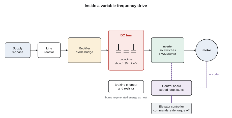
A control board runs the drive. It receives commands from the elevator controller, such as run up, run down, the speed pattern and the stop, and it closes the speed loop using an encoder on the motor shaft. It also monitors bus voltage, output currents, temperatures and the encoder signal, and it trips the drive with a fault code if anything is out of range. The fault code is usually the first clue a mechanic gets.
Voltage and frequency together
An induction motor's flux depends on the ratio of applied voltage to frequency. If the frequency is reduced to run the motor slowly but the voltage is left at full value, the flux rises, the iron saturates and the magnetizing current becomes very large. If the voltage is reduced too far, the flux falls and the motor loses torque. The simplest drive control keeps the ratio constant, so that at half speed the motor gets half voltage at half frequency. This is volts-per-hertz control.
# Constant volts per hertz for a 575 V, 60 Hz induction hoist motor
v_rated, f_rated = 575.0, 60.0
boost = 25            # extra volts at low frequency to cover the stator resistance drop
for f in (1, 3, 10, 20, 30, 45, 60):
    v = min(v_rated, boost + (v_rated - boost) * f / f_rated)
print(f"{f:3d} Hz -> {v:5.0f} V ({v / f:5.1f} V/Hz)")1 Hz -> 34 V ( 34.2 V/Hz) 3 Hz -> 52 V ( 17.5 V/Hz) 10 Hz -> 117 V ( 11.7 V/Hz) 20 Hz -> 208 V ( 10.4 V/Hz) 30 Hz -> 300 V ( 10.0 V/Hz) 45 Hz -> 438 V ( 9.7 V/Hz) 60 Hz -> 575 V ( 9.6 V/Hz)
At low frequency the voltage drop in the stator winding's resistance becomes a large part of the applied voltage, so a little extra voltage, the boost, is added to keep the flux up. Volts-per-hertz control is adequate for fans and pumps, but it cannot give an elevator the precise torque control it needs at zero speed, when the brake lifts with the car loaded. Elevator drives use vector control instead: from the encoder position and the measured currents, the drive calculates the flux and torque in the motor at every instant and controls them separately, much as a DC drive controls field and armature current. For a permanent-magnet machine, vector control is the only option, because the drive must keep its field aligned with the rotor magnets.
The speed pattern
A drive does not simply switch the car to full speed. The controller and drive follow a speed pattern: the brake lifts while the drive holds the car at zero speed with full torque, then the car accelerates with a controlled rate of change of acceleration, called jerk, so that passengers feel a gentle start; it runs at contract speed, decelerates on a pattern calculated from the distance to the floor, approaches at a low levelling speed for the last few centimetres, and stops at floor level, where the drive holds zero speed again while the brake sets. Only then does the drive remove torque and the controller open the motor contactors. This start and stop under drive control, with the brake only holding a stationary car, is why a modern traction car stops more accurately and more quietly than the old two-speed cars.
Motoring and regenerating
Lesson 9 showed that a traction hoist motor sometimes draws power and sometimes generates it. The direction of the car and the direction of the torque together decide which. When the motor turns in the direction it is pushing, it is motoring: a full car going up, or an empty car going down. When the load drives the motor against the torque it is applying, it is regenerating: an empty car going up, with the heavier counterweight pulling the machine round; a full car going down; and any car decelerating, when the moving masses give back their kinetic energy.
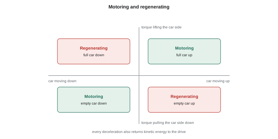
When the motor regenerates, current flows from the motor back through the inverter into the DC bus, and the bus voltage rises. A six-pulse diode rectifier cannot send energy back to the supply, because diodes conduct in one direction only, so the energy has to go somewhere else. If nothing absorbs it, the bus voltage climbs until the drive trips on overvoltage, typically at about 1.2 to 1.3 times its normal level, and the car stops abruptly.
There are two solutions. The first is a braking chopper and resistor: a transistor across the bus connects an external resistor when the bus voltage rises above a set level, and the resistor turns the energy into heat. Braking resistors on elevator drives are large, mounted on the controller or in the control space, and they get hot; they are guarded so that nobody can touch them and are kept clear of combustibles. The second solution is a regenerative drive, which replaces the diode rectifier with an active front end of transistors that can send energy back to the building supply as clean 60 Hz power. The Quayside cars have regenerative drives, and the energy the cars give back during their many light up-trips and heavy down-trips is used by other loads in the building.
# Energy regenerated on one Quayside trip and braking resistor duty (illustrative)
car, Q, K = 1500, 1600, 0.45             # empty car, rated load (kg), overbalance
cwt = car + K * Q
rise = 87                            # travel, ground to top, m
v = 2.5                                  # car speed, m/s
eta = 0.85
for name, load, up in (("empty car up", 0, True), ("full car down", Q, False)):
    unbalance = cwt - (car + load) if up else (car + load) - cwt   # mass driving the machine
    e_back = unbalance * 9.81 * rise * eta * 1                   # J reaching the DC bus
    p_back = unbalance * 9.81 * v * eta * 1                      # W during the steady run
    print(f"{name:<14} driving mass {unbalance:5.0f} kg, energy to the bus {e_back / 3.6e6:.3f} kWh, "
          f"power {p_back / 1000:5.1f} kW")
# a braking resistor that must absorb that power without a regenerative front end
v_bus = 950            # V at which the chopper switches the resistor in
p = (cwt - car) * 9.81 * v * eta * 1                            # W
r = v_bus ** 2 / (1.5 * p)          # sized to take 1.5 x the steady power
print(f"resistor of about {r:.0f} ohm takes {v_bus ** 2 / r / 1000:.1f} kW at {v_bus} V")empty car up driving mass 720 kg, energy to the bus 0.145 kWh, power 15.0 kW full car down driving mass 880 kg, energy to the bus 0.177 kWh, power 18.3 kW resistor of about 40 ohm takes 22.5 kW at 950 V
Each of these trips returns between one and two tenths of a kilowatt-hour, which seems small, but a busy residential car makes hundreds of trips a day, and in a building with several cars the total is significant. On a drive with a braking resistor the same energy is turned into heat in the control space, which also has to be ventilated.
Drive faults and what they mean
| Fault | What the drive saw | Common causes |
|---|---|---|
| Overvoltage | DC bus voltage too high | Braking resistor open or disconnected, chopper failed, deceleration too fast, high supply voltage |
| Undervoltage | DC bus too low | Supply sag, phase loss, failed precharge circuit |
| Overcurrent | Output current beyond the limit | Short in motor leads, mechanical binding, brake not lifting, wrong motor data or encoder offset |
| Ground fault | Unbalanced output currents | Damaged motor lead insulation, moisture in the motor |
| Encoder fault | Lost or implausible encoder signal | Loose encoder connector, damaged cable, shield not grounded, encoder failure |
| Overtemperature | Heatsink too hot | Blocked cooling fan or filter, high ambient in the control space |
Priya's advice on drive faults is to read and record the fault code and the fault log before resetting anything, because many drives store the bus voltage, current and speed at the moment of the fault, and that snapshot is often more informative than anything the mechanic can measure afterwards. A drive that trips on overvoltage only on down runs with a full car, for example, almost certainly has a braking resistor or chopper problem, because that is when the most energy comes back.
Practical hazards of drives
Drives bring their own electrical hazards. The DC bus stays charged after the drive is off, as Lesson 1 described. The output to the motor is a train of fast pulses, which can produce voltage spikes at the motor terminals on long leads and currents through the motor bearings; shielded motor cables, correctly grounded at both ends, and output filters are used to control them. The pulses also interfere with nearby signal wiring, so encoder and control cables are run separately from motor leads. And a drive draws a distorted current from the supply, rich in harmonics, which is reduced with a line reactor at the input. A mechanic replacing a motor lead or an encoder cable on a drive installation follows the manufacturer's routing and grounding instructions exactly, because shortcuts that work on a relay controller produce intermittent faults on a drive.
Modern drives also include a safe torque off function: a hardware input, independent of the drive's software, that removes the gate signals from the inverter switches so that the motor cannot produce torque. Elevator codes now permit certified electronic safety functions of this kind to replace some of the traditional motor contactors, and the Quayside controllers use one contactor plus safe torque off rather than two contactors. Safe torque off prevents motion but does not remove voltage: the bus and the motor leads may still be live, so it is never a substitute for lockout.
Worked problem
Overvoltage trips on a modernized car
A Northcrest crew has just modernized a five-stop traction car at an office building on Route 7 with a new drive and a braking resistor. The car runs well on test, but in its first week it trips on DC bus overvoltage a few times a day, always near the end of a run. What should the crew look at?
Show solution
- Overvoltage means energy is coming back faster than the drive is getting rid of it. That happens during regeneration: light car up, heavy car down, and every deceleration.
- Trips near the end of a run point to deceleration, when the moving masses give up their kinetic energy, possibly combined with regeneration from the load.
- The first checks are the braking resistor and chopper: is the resistor connected, does it measure the specified resistance cold, and does the drive's parameter for the chopper match the resistor fitted?
- The crew finds the resistor correct but the chopper enable parameter left off from the factory default. With it set, the bus voltage rises only to the chopper's threshold and the trips stop.
Answer: Overvoltage near the end of runs is a braking path problem; the chopper had not been enabled in the drive parameters.
Common mistakes
MistakeAssuming the motor leads are dead because safe torque off is active.
InsteadSafe torque off stops torque, not voltage; lock out and verify.
MistakeResetting a drive fault without recording the fault log.
InsteadRecord the code and the snapshot data first.
MistakeRunning encoder cables alongside the motor leads.
InsteadSeparate signal and power wiring and ground shields as specified.
MistakeFitting any resistor of similar wattage as a braking resistor.
InsteadUse the resistance and rating the drive manufacturer specifies; too low a resistance can damage the chopper.
MistakeTreating volts-per-hertz as enough for a hoist motor.
InsteadElevator drives use vector control with encoder feedback for torque at zero speed.
Summary and key terms
- A drive rectifies the supply to a DC bus, then inverts it to variable voltage and frequency with pulse-width modulation.
- Volts-per-hertz keeps induction motor flux steady; elevator drives use vector control with an encoder.
- The drive holds the car at zero speed while the brake lifts and sets, and follows a smooth speed pattern between.
- Light cars up, heavy cars down and decelerating cars regenerate energy into the DC bus.
- Regenerated energy is burnt in a braking resistor or returned to the supply by a regenerative front end.
- Drive faults, recorded before reset, point to the cause; safe torque off is not lockout.
- Variable-frequency drive
- Equipment that supplies a motor with variable voltage and frequency from a fixed supply.
- DC bus
- The capacitor-smoothed DC link between the rectifier and the inverter.
- Pulse-width modulation
- Building an average sine-wave voltage from fast pulses of varying width.
- Vector control
- Drive control that regulates motor flux and torque separately from measured currents and rotor position.
- Regeneration
- Operation in which the motor acts as a generator and returns energy to the drive.
- Braking resistor
- A resistor switched across the DC bus to absorb regenerated energy as heat.
- Safe torque off
- A certified drive function that removes the inverter's ability to produce torque without removing voltage.
Practice problems
Work each problem on paper first, then reveal the answer to check.
What DC bus voltage would you expect on a drive fed at 480 V? At 600 V?
Show answer
About 1.35 × 480 = 650 V; about 1.35 × 600 = 810 V.
Under constant volts per hertz, what voltage does a 460 V, 60 Hz motor get at 30 Hz?
Show answer
About 230 V, plus any low-speed boost.
Name the two traction elevator conditions in which the motor regenerates at steady speed.
Show answer
An empty or lightly loaded car going up, and a full or heavily loaded car going down.
A drive trips on overvoltage only when a full car runs down. What do you suspect first?
Show answer
The braking resistor or chopper, or the regenerative front end if fitted.
Lesson quiz · 5 questions
Score 60% or more to complete this lesson.
Create a free account to save your progress, take quizzes and earn a certificate.