
ELV-210 · Lesson 3 of 12 · 20 min
Series, parallel and control circuits
Real circuits have more than one component, and the way the components are connected decides how they behave. Two arrangements cover almost everything in an elevator controller. In a series circuit the components are connected end to end in a single path, so the same current passes through all of them. In a parallel circuit they are connected across the same two points, so each has the same voltage and the current divides among them. Priya tells the class that if they understand these two arrangements, they understand the safety circuit of every elevator they will ever work on, because the safety circuit is the most important series circuit in the building.
Series circuits
When resistances are connected in series, the total resistance is their sum. The same current flows through each, and the supply voltage is shared among them in proportion to their resistances.
The sharing of voltage is the heart of troubleshooting. Kirchhoff's voltage law says that around any closed loop, the voltage rises from the supply equal the voltage drops across the components. In a series circuit of a supply and three resistors, the three drops add up to the supply voltage. A component with more resistance takes a larger share. This is the voltage divider, and the voltage across one resistor in a series string is the supply voltage times that resistor's fraction of the total.
Now consider what that means for a string of switch contacts. A closed contact in good condition has almost no resistance, so it takes almost no voltage. An open contact has, in effect, infinite resistance, so it takes all of the voltage. If a 120 V string of twelve contacts feeds a relay coil and one contact is open, a meter across that contact reads 120 V and a meter across any of the closed ones reads zero. A contact that is closed but dirty, with a resistance of a few ohms or more, takes a share proportional to its resistance and robs the coil of voltage. These three readings, zero, full voltage and something in between, are what a mechanic looks for when testing a string.
Parallel circuits
When resistances are connected in parallel, each one is connected across the same two points and has the full supply voltage across it. Each draws its own current by Ohm's law, and the total current is the sum of the branch currents. That is Kirchhoff's current law: the current into a junction equals the current out of it.
The total resistance of a parallel group is always less than the smallest branch resistance, because every branch adds another path. For two resistors, the total is their product divided by their sum. For a number of identical loads, it is the resistance of one divided by the number. A row of hall lanterns, the lamps in a car operating panel and the coils of several relays fed from the same control bus are all parallel loads. Removing one does not affect the others, and the total current tells you how many are drawing.
Parallel circuits explain why a single short circuit blows the fuse for a whole group. A short is a branch with almost no resistance in parallel with all the others, and it draws a very large current. It also explains a common surprise on older equipment: a lamp that glows dimly when it should be off. That usually means a leakage path, such as a damp fixture or a damaged insulation, in parallel with the switch that is supposed to keep it dark.
# Parallel loads on a 24 V DC lamp and indicator bus in a car operating panel
supply = 24.0
loads = {  # name: (number, resistance of one, ohms)
    "button lamps": (14, 1200),
    "position indicator": (1, 96),
    "hall lantern relays": (4, 480),
}
total_i = 0
for name, (n, r) in loads.items():
    i = n * supply / r
    total_i += i
    print(f"{name:<20} {n:2d} x {r:5d} ohm -> {i:5.3f} A")
print(f"total current {total_i:.3f} A, total resistance {supply / total_i:.1f} ohm")
print(f"power from the supply {supply * total_i:.1f} W")button lamps 14 x 1200 ohm -> 0.280 A position indicator 1 x 96 ohm -> 0.250 A hall lantern relays 4 x 480 ohm -> 0.200 A total current 0.730 A, total resistance 32.9 ohm power from the supply 17.5 W
Series and parallel as logic
Control circuits use contacts in series and parallel to make decisions. Contacts in series act as AND: every one must be closed for current to flow. Contacts in parallel act as OR: any one closed is enough. An up-direction run circuit, for example, might require the safety string AND the door lock string AND an up direction signal AND no down direction contactor energized. A car call button circuit might register a call if the button in the car is pressed OR a call is already registered and its holding contact is closed. Lesson 7 shows how relays hold themselves in, and Lesson 11 how these arrangements are drawn on a wiring diagram, but the electrical rules are the ones in this lesson.
| Arrangement | Logic | Elevator example |
|---|---|---|
| Contacts in series | AND: all must be closed | The safety string: pit stop switch, buffer switches, governor switch, final limits, car top stop switch |
| Contacts in parallel | OR: any one closed | A call registered from the car button or held in by its own contact |
| Normally closed contact in series | NOT: the other device must be off | The up contactor coil is fed through a closed contact of the down contactor |
| Series group in parallel with another | Either path may complete the circuit | Normal operation or inspection operation feeding the same run relay through different switches |
The safety circuit
Every elevator has a safety circuit, often called the safety string: a series chain of normally closed contacts, each belonging to a device that must stop the car if it operates. The string feeds a safety relay, or on modern controllers a safety input monitored by a certified safety processor. If any contact opens, the relay drops, the brake sets and the drive is disconnected or blocked. The devices in the string on a traction elevator typically include the pit stop switch, the buffer switches if the buffers require them, the governor overspeed switch and the governor tension sheave switch, the car safety operated switch, the final terminal limits at top and bottom, the car top stop switch, the emergency stop switch in the car where one is fitted, the machine room or control space stop switch, and others that vary with the equipment.
The door lock and gate circuits are related series strings. Each hoistway door has an interlock with an electrical contact that is closed only when the door is closed and mechanically locked, and the car door has its own contact. These contacts are often wired as a separate string so that the controller can tell the difference between a safety fault and an open door. The car may not move under normal operation unless both strings are complete.
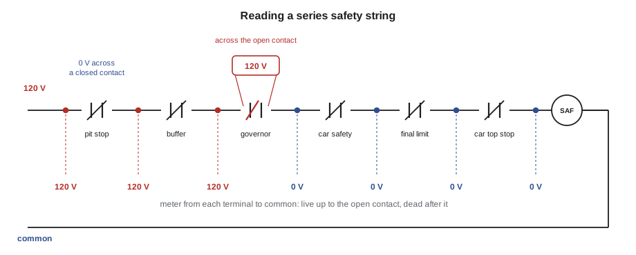
Because the string is in series, finding an open contact is a matter of following the voltage. Ray's method, which Tamsin practises in the branch training room on a demonstration board, is to put one meter lead on the common return and walk the other lead down the string, terminal by terminal, from the supply end. Every terminal before the open contact reads full voltage to common; every terminal after it reads zero. The open contact sits between the last good reading and the first dead one. A second method, measuring across each contact in turn, gives full voltage across the open one and zero across the rest. Both are done with the circuit energized, by a qualified person with the right PPE, and neither needs a jumper.
# Node voltages along a 120 V safety string, measured to common
supply = 120.0
coil = 2400.0                      # safety relay coil resistance, ohms
contacts = [("pit stop", 0.05), ("buffer", 0.05), ("governor", 0.05),
            ("car safety", 0.05), ("final limit", 35.0), ("car top stop", 0.05)]
# case 1: a dirty final limit contact; case 2: the governor switch open
for case in ("dirty final limit", "governor open"):
    rs = [(n, 1e12 if (case == "governor open" and n == "governor") else r) for n, r in contacts]
    total = sum(r for _, r in rs) + coil
    i = supply / total
    v = supply
    print(case)
    for n, r in rs:
        print(f"  before {n:<13} {v:6.1f} V")
        v -= i * r
print(f" at the relay coil {v:6.1f} V (pickup needs about 85 V)")dirty final limit before pit stop 120.0 V before buffer 120.0 V before governor 120.0 V before car safety 120.0 V before final limit 120.0 V before car top stop 118.3 V at the relay coil 118.3 V (pickup needs about 85 V) governor open before pit stop 120.0 V before buffer 120.0 V before governor 120.0 V before car safety 0.0 V before final limit 0.0 V before car top stop 0.0 V at the relay coil 0.0 V (pickup needs about 85 V)
The first case is the subtle one. The dirty final limit contact has 35 ohms in it, small compared with the 2,400-ohm coil, so the coil still gets most of the voltage and the relay still picks up. But if the contact gets worse, or if several contacts are a little dirty, the coil voltage drifts down towards the point where the relay drops out on a vibration. That is how intermittent safety faults begin: a car that trips occasionally on a rough start, with nothing found when the mechanic arrives. A careful mechanic on a maintenance visit measures across each contact while the car runs, and a reading of a volt or two across a closed contact is a reason to clean or replace it.
Series-parallel circuits and reduction
Most real circuits combine both arrangements. They are analysed by reduction: combine any resistances that are purely in series or purely in parallel into one equivalent, redraw, and repeat until a single resistance remains. Then work back out, finding the current and voltage in each part. The method is mechanical and reliable as long as each step really is a pure series or pure parallel combination.
Worked problem
Hall lanterns on a shared supply
At Brackenridge Centre, the escalator direction indicators and a pair of warning lamps at the lower landing are fed from a 24 V DC supply through a run of cable with a loop resistance of 1.5 ohms. The two direction indicators are 48 ohms each, in parallel, and the pair of warning lamps, 120 ohms each, are in parallel with them. What voltage reaches the lamps?
Show solution
- Combine the four parallel loads: 1 / R = 1/48 + 1/48 + 1/120 + 1/120 = 0.0583, so R = 17.1 ohms.
- Add the cable in series: total = 17.1 + 1.5 = 18.6 ohms.
- Current from the supply: 24 / 18.6 = 1.29 A.
- Drop in the cable: 1.29 × 1.5 = 1.94 V, so the lamps see 24 − 1.94 = 22.1 V.
Answer: About 22 V reaches the lamps, a drop of about 8 percent; adding more lamps would increase the current and the drop.
Grounds and short circuits
Control circuits are normally referenced to ground at one point, usually by bonding one side of the control transformer secondary or one side of the DC supply to the equipment ground. That makes a fault predictable. If an insulated conductor on the live side of a safety circuit chafes through and touches the grounded frame, the current takes the short path to ground, the fuse blows and the car stops. The design ensures that a ground fault causes a shutdown rather than a hidden bypass. If both sides of a contact were shorted to ground, however, the contact would be bypassed, and the car could run with that device open. That is why the codes require the circuits to be arranged so that a single ground or a single failed component does not make a safety device ineffective, and why mechanics never move the ground reference of a control circuit.
Common mistakes
MistakeMeasuring across a closed contact, reading zero, and deciding the circuit has no power.
InsteadZero across a closed contact is normal; measure to common to see whether the circuit is live.
MistakeAssuming adding a load in parallel increases the total resistance.
InsteadEach parallel branch adds a path; total resistance goes down and total current goes up.
MistakeIgnoring a volt or two across a closed safety contact.
InsteadA closed contact should read almost zero; a few volts means resistance that will worsen.
MistakeJumping the string to see whether the car will run.
InsteadFind the open contact with the meter; jumpers are controlled and never used to run a car.
MistakeReducing a circuit by combining resistances that are neither purely series nor purely parallel.
InsteadOnly combine pure series or pure parallel groups at each step.
Summary and key terms
- Series components share one current, and their resistances add.
- In a series string, the open contact takes the full supply voltage and the closed ones take almost none.
- Parallel components share one voltage, their currents add, and the total resistance is less than the smallest branch.
- Series contacts make AND decisions, parallel contacts make OR decisions.
- The safety string is a series chain of normally closed contacts that stops the car if any opens.
- Following the voltage to common, or measuring across each contact, finds an open or a resistive contact without a jumper.
- Series circuit
- Components connected end to end in one path carrying the same current.
- Parallel circuit
- Components connected across the same two points, each with the same voltage.
- Kirchhoff's voltage law
- Around a closed loop, the sum of voltage rises equals the sum of voltage drops.
- Kirchhoff's current law
- The current into a junction equals the current out of it.
- Voltage divider
- A series circuit in which each resistance takes a share of the supply proportional to its value.
- Safety string
- The series chain of safety device contacts that must all be closed for the car to run.
- Door lock string
- The series chain of hoistway door interlock and car door contacts.
Practice problems
Work each problem on paper first, then reveal the answer to check.
Resistances of 10, 20 and 30 ohms are in series across 120 V. What current flows, and what is the drop across the 30-ohm resistor?
Show answer
Total 60 ohms; I = 2 A; drop = 2 × 30 = 60 V.
What is the total resistance of 100 ohms and 400 ohms in parallel?
Show answer
100 × 400 / 500 = 80 ohms.
Twelve contacts in series feed a 120 V coil. One is open. What does a meter read across the open contact, and across each closed one?
Show answer
120 V across the open contact, 0 V across each closed one.
Six identical 600-ohm relay coils are in parallel on 24 V. What is the total current?
Show answer
Each draws 0.04 A; total 0.24 A (total resistance 100 ohms).
Lesson quiz · 5 questions
Score 60% or more to complete this lesson.
Create a free account to save your progress, take quizzes and earn a certificate.