
ELV-210 · Lesson 5 of 12 · 19 min
AC fundamentals and power factor
The power that reaches an elevator from the utility is alternating current, and much of what happens inside the controller is AC too: the control transformer, AC relay and contactor coils, door operator motors, fans and the hoist motor itself on most installations. Alternating current behaves like DC in a resistor, but it behaves differently in coils and capacitors, and those differences explain several things Tamsin has already seen on the job without understanding them: why a contactor coil hums and burns out if its armature sticks, why a motor's current is not simply its power divided by its voltage, and why the voltage on a meter is not the highest voltage in the circuit.
The sine wave
An AC voltage reverses direction many times a second. The utility supply follows a sine wave: it rises from zero to a positive peak, falls back through zero to a negative peak and returns to zero, then repeats. One complete repetition is a cycle. The number of cycles per second is the frequency, in hertz. North American utilities supply 60 Hz, so one cycle lasts one sixtieth of a second, about 16.7 milliseconds. The time for one cycle is the period.
Because the voltage is always changing, it needs a way to be described by a single number. The peak value is the highest point of the wave. The RMS value, or effective value, is the DC voltage that would deliver the same power to a resistor. For a sine wave the peak is the square root of two, about 1.414, times the RMS value. When a meter reads 120 V AC, it shows the RMS value; the voltage actually swings to about 170 V at each peak. On a 600 V supply the line-to-line peak is about 850 V.
The peak value matters for insulation and for components that charge to it. A rectifier and capacitor fed from 120 V AC charges the capacitor to nearly 170 V DC, not 120, and the DC bus of a drive on a 600 V supply charges to roughly the line-to-line peak, which is where the 1.35 to 1.4 factor from Lesson 1 comes from.
Resistance, inductance and capacitance in AC
In a pure resistance, the current follows the voltage exactly: it rises and falls at the same instants. The current is the voltage divided by the resistance, as in DC, and the power is the RMS voltage times the RMS current.
A coil of wire has inductance. When the current in it changes, its magnetic field changes, and the changing field induces a voltage that opposes the change. In a DC circuit this only matters when the current is switched on or off. In an AC circuit the current is always changing, so a coil always opposes it. The opposition is called inductive reactance, measured in ohms. It rises with the frequency and with the inductance.
A capacitor stores charge on plates separated by insulation. In an AC circuit it charges and discharges every half cycle, so current flows to and from it continuously even though no current crosses the insulation. Its opposition, capacitive reactance, falls as frequency rises. Inductive and capacitive reactance also shift the timing of the current. In an inductor, the current lags the voltage by a quarter cycle, ninety degrees. In a capacitor, it leads by ninety degrees. Real coils have both resistance and inductance, and the current lags by some angle between zero and ninety degrees.
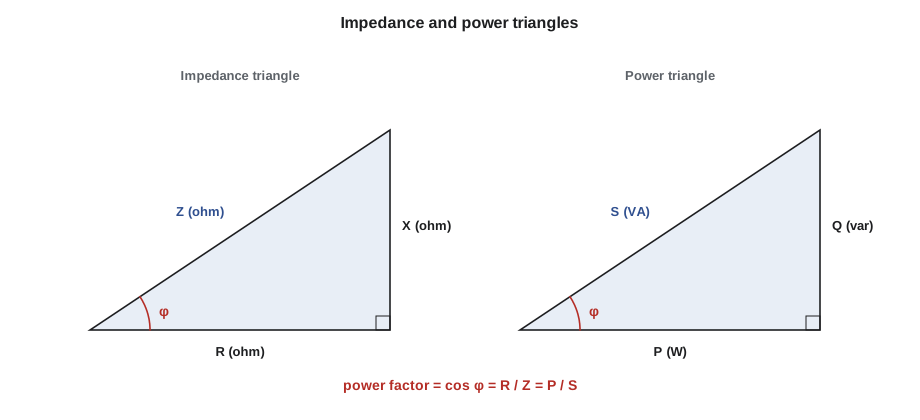
The combined opposition of resistance and reactance is the impedance, also in ohms. Because the resistance and reactance act ninety degrees apart, they combine like the sides of a right triangle, not by simple addition. The angle of the triangle is the phase angle between voltage and current.
Why an AC contactor burns out when it sticks
An AC relay or contactor coil is wound on a laminated iron core. When the contactor is open, there is an air gap between the core and the armature, the magnetic circuit is poor, and the coil's inductance is low. When the coil is energized and the armature pulls in, the gap closes, the inductance rises several times, and the reactance rises with it. The result is that an AC coil draws a large inrush current when it first operates, often five to ten times its holding current, and then settles down. If anything stops the armature from closing, such as dirt, a mechanical jam or a voltage too low to pull it in, the coil stays at its high inrush current, overheats and burns out within minutes.
# AC contactor coil on 120 V, 60 Hz: open and closed armature (illustrative)
import math
v, f = 120.0, 60.0
R = 22.0                                     # coil resistance, ohms
for state, L in (("armature open (sealing)", 0.075), ("armature closed (holding)", 0.60)):
    xl = 2 * math.pi * f * L
    z = math.sqrt(R ** 2 + xl ** 2)
    i = v / z
    pf = R / z
    heat = i ** 2 * R
print(f"{state:<26} XL {xl:6.1f} Z {z:6.1f} ohm I {i:5.2f} A pf {pf:4.2f} coil heat {heat:5.1f} W")armature open (sealing) XL 28.3 Z 35.8 ohm I 3.35 A pf 0.61 coil heat 246.8 W armature closed (holding) XL 226.2 Z 227.3 ohm I 0.53 A pf 0.10 coil heat 6.1 W
The coil produces about fifty times as much heat with the armature open as with it closed. That is the reason Ray examines a burnt contactor coil before replacing it: if the new coil goes into the same contactor with the same sticking armature or the same low supply voltage, it will burn out too. DC coils do not have this problem, because their current is set by resistance alone, which is one reason many modern controllers use DC coils on their main contactors.
Power in AC circuits
In a circuit with reactance, the voltage and current are not in step, and the product of the RMS voltage and current overstates the real power. Part of each cycle the coil or capacitor takes energy from the supply to build its field, and part of each cycle it gives it back. That energy flows back and forth without doing work, but the current that carries it still flows in the wires.
Three quantities describe the power. Real power, in watts, is the rate at which energy is actually converted to heat, light or motion. Reactive power, in volt-amperes reactive, or vars, is the back-and-forth flow to the magnetic and electric fields. Apparent power, in volt-amperes, is the product of RMS voltage and RMS current, and it is what the wires, fuses and transformers must carry. They form the power triangle, and the ratio of real to apparent power is the power factor.
A resistive heater has a power factor of 1. An induction motor running at full load typically has a power factor of about 0.8 to 0.88, and at light load much lower, perhaps 0.3 to 0.5, because it still draws the magnetizing current that sets up its field. That is why the current drawn by the motor of a hydraulic elevator pump running unloaded is not much less than at full load: much of the current is reactive. The utility charges large customers for poor power factor, and for that reason buildings sometimes add capacitors to supply the reactive power locally.
# Holloway car 1 pump motor: power triangle and capacitor correction (illustrative)
import math
v_line = 600.0          # V line to line, three-phase
p_kw = 30.0            # real power drawn at full load, kW
pf = 0.84
s_kva = p_kw / pf
q_kvar = math.sqrt(s_kva ** 2 - p_kw ** 2)
i = s_kva * 1000 / (math.sqrt(3) * v_line)
print(f"S {s_kva:5.1f} kVA, Q {q_kvar:5.1f} kvar, line current {i:5.1f} A")
# capacitors to raise the power factor to 0.95
pf_new = 0.95
q_new = p_kw * math.tan(math.acos(pf_new))
i_new = (p_kw / pf_new) * 1000 / (math.sqrt(3) * v_line)
print(f"to reach pf {pf_new}: supply {q_kvar - q_new:4.1f} kvar from capacitors")
print(f"line current falls to {i_new:5.1f} A ({100 * (1 - i_new / i):.0f} % less)")S 35.7 kVA, Q 19.4 kvar, line current 34.4 A to reach pf 0.95: supply 9.5 kvar from capacitors line current falls to 30.4 A (12 % less)
The calculation uses the three-phase formula that Lesson 6 explains. Correcting the power factor reduces the current in the feeder, which reduces voltage drop and heating in the building's wiring, while the motor itself draws the same real power. Capacitors are not normally fitted on elevator motors controlled by drives, because the drive's own rectifier and the switching of the inverter interact badly with them, and a drive already draws its supply current at a high power factor.
AC on a meter and on a coil
Two practical points follow for Tamsin's work. First, a coil cannot be checked by measuring its resistance alone. A 120 V AC contactor coil with a DC resistance of 22 ohms is not faulty just because Ohm's law with 22 ohms predicts more than five amperes. Its impedance, not its resistance, sets the current. Second, an AC coil should never be fed from a DC supply of the same voltage, and a DC coil should never be fed from AC. On DC, an AC coil's low resistance lets a large current flow and it burns out. On AC, a DC coil's inductance limits its current, so it chatters and fails to pull in. Coils are marked with their voltage and whether it is AC or DC, and replacements must match both.
Worked problem
Checking a door operator motor current
The car door operator on Delmont Hotel's freight elevator is a single-phase 120 V AC motor. Its nameplate gives 1/4 hp output, 2.8 A full-load current and a power factor of 0.70. Tamsin measures 2.4 A with a clamp meter during a door opening. What real power is it drawing, and is the current reasonable?
Show solution
- Apparent power at the measured current: 120 × 2.4 = 288 VA.
- Real power at the nameplate power factor: 288 × 0.70 = 202 W. (A quarter horsepower is about 186 W of output, so the motor is working near its rating during the opening stroke.)
- 2.4 A is below the 2.8 A full-load current, as expected for a door that runs freely.
- If the current rose toward or above 2.8 A over time, Ray would look for a binding door hanger, a tight gib or a misaligned clutch.
Answer: About 200 W of real power from 288 VA apparent; the current is normal, and a rising current would point to mechanical drag.
Capacitors in elevator equipment
Capacitors appear in several places a mechanic will meet them. Small single-phase motors, such as the door operator motors on older cars and the fans in controller cabinets, are often capacitor-run motors: a capacitor in series with a second winding shifts the current in that winding by close to ninety degrees, which gives the motor a rotating field and lets it start and run in one direction. If the capacitor fails, the motor hums, starts slowly, runs hot or will not start at all, and it may run in either direction if pushed by hand. Run capacitors are rated in microfarads and in AC volts, and a replacement must match both. A capacitance meter, or the capacitance function on Tamsin's multimeter, tests them once they are disconnected and discharged.
Capacitors also filter DC supplies and drive buses, suppress interference across contacts and coils, and correct power factor on some across-the-line motors. All of them store energy. A capacitor charged to the peak of the supply can hold that voltage after the power is removed, so a capacitor is discharged through a suitable resistor, and its voltage is measured, before it is handled. Ray keeps a discharge tool with an insulated handle and a built-in resistor in his kit for exactly this, and he never discharges a capacitor by shorting it with a screwdriver, which can weld the tip and scatter molten metal.
Common mistakes
MistakeTaking the meter reading of 120 V as the highest voltage in the circuit.
InsteadThe peak is about 1.414 times the RMS reading, about 170 V.
MistakePredicting an AC coil's current from its DC resistance.
InsteadUse impedance; reactance limits AC current.
MistakeReplacing a burnt AC contactor coil without finding why it burnt.
InsteadCheck for a sticking armature or low supply voltage first.
MistakeFitting a DC coil where an AC coil was, or the reverse.
InsteadMatch the coil's voltage and whether it is AC or DC.
MistakeCalculating motor power as volts times amps.
InsteadReal power is V × I × power factor.
Summary and key terms
- AC follows a sine wave at 60 Hz; meters show RMS values, and the peak is about 1.414 times the RMS.
- Inductive reactance rises with frequency, and current in an inductor lags the voltage; capacitors make the current lead.
- Impedance combines resistance and reactance at right angles.
- AC contactor coils draw high inrush current until the armature closes, and burn out if it sticks.
- Real, reactive and apparent power form a right triangle; power factor is real over apparent power.
- Induction motors have low power factor at light load; capacitors can correct it on across-the-line motors.
- Frequency
- The number of AC cycles per second, in hertz.
- RMS value
- The effective value of an AC quantity, equal in heating effect to the same DC value.
- Inductive reactance
- The opposition of an inductance to alternating current, 2πfL.
- Impedance
- The total opposition to AC, combining resistance and reactance.
- Phase angle
- The angle by which the current lags or leads the voltage.
- Power factor
- The ratio of real power to apparent power, cos φ for sine waves.
- Reactive power
- Power that flows back and forth to magnetic or electric fields, in vars.
Practice problems
Work each problem on paper first, then reveal the answer to check.
A meter reads 240 V AC. What is the peak voltage?
Show answer
240 × 1.414 = about 339 V.
What is the reactance of a 0.5 H coil at 60 Hz?
Show answer
2π × 60 × 0.5 = 188 ohms.
A coil has R = 30 ohms and X = 40 ohms. What is its impedance and power factor?
Show answer
Z = √(30² + 40²) = 50 ohms; pf = 30 / 50 = 0.6.
A single-phase load draws 10 A at 120 V with a power factor of 0.8. What are P, S and Q?
Show answer
S = 1,200 VA; P = 960 W; Q = √(1,200² − 960²) = 720 var.
Lesson quiz · 5 questions
Score 60% or more to complete this lesson.
Create a free account to save your progress, take quizzes and earn a certificate.