
ELV-130 · Lesson 2 of 12 · 20 min
Load weight and centre of gravity
The first of Ray's five questions is what the load weighs, and the second is where its centre of gravity is. Every other decision in a lift depends on these two answers: the size of the hoist and slings, the rigging points, the sling angles, and the way the load will hang when it leaves the ground. A weight that is wrong by a quarter turns a safe lift into an overloaded one, and a centre of gravity in the wrong place turns a level lift into a load that tips, slides out of its slings or swings into a rail. This lesson covers where weights come from, how to estimate them when nobody has written them down, how to find the centre of gravity of a load made of several parts, and what the centre of gravity does to the loads in the rigging.
Where the weight comes from
The best source of a weight is a document from the manufacturer: the nameplate on the equipment, the shipping documents, the installation manual or the drawing. The Quayside machine has its weight on its nameplate and in the manual. The car sling parts are listed on the packing list with their weights. Even then, Ray reads the number critically. A packing list weight may be for the crate rather than the part, or for a pallet of several parts, and a manual may give the weight of the machine without the brake, the encoder bracket or the bedplate that will be bolted to it for the lift. The weight that matters is the weight of exactly what will hang from the hook.
Weighing is the next best source. A load cell or crane scale hung between the hoist hook and the rigging reads the actual weight when the load is lifted a little way off its supports. Northcrest carries a small load cell in the branch for loads whose weight is uncertain, such as an old machine that has been modified over the years. A forklift or pallet jack with a scale can weigh smaller items before they go to the hoistway.
When there is no document and no scale, the weight is calculated from the dimensions of the load and the density of its material. This is the usual case for old equipment on a modernization, for fabricated steel such as a temporary rigging beam, and for anything that has been cut or modified. A calculated weight is rounded up, and the rigging is sized for the rounded figure.
| Material | Density | Note |
|---|---|---|
| Steel | 7,850 kg/m³ (490 lb/ft³) | Rails, frames, bedplates, beams |
| Cast iron | 7,200 kg/m³ (450 lb/ft³) | Old machine housings, counterweight fillers |
| Aluminum | 2,700 kg/m³ (170 lb/ft³) | Cab panels, some platforms |
| Concrete | 2,400 kg/m³ (150 lb/ft³) | Concrete counterweight fillers on old cars |
| Lead | 11,300 kg/m³ (710 lb/ft³) | Small trim weights |
| Hydraulic oil | 870 kg/m³ (54 lb/ft³) | Tank contents of a hydraulic power unit |
| Dry softwood | 500 kg/m³ (31 lb/ft³) | Crating, cribbing timbers |
Estimating a weight from dimensions
To estimate a weight, break the load into simple shapes, find the volume of each, multiply by the density, and add the parts. A steel plate is length times width times thickness. A hollow section is the outside volume minus the inside volume. A round bar or a sheave is a cylinder. Holes and cut-outs are subtracted only when they are large; small bolt holes are ignored, which errs on the heavy side. Ray adds a margin to every calculated weight, usually ten percent, because welds, paint, bolts and the bits nobody measured always add up.
On the Tillicum Building job on Route 7, the old geared machine on car 2 has no nameplate weight, and the original drawings are long gone. Tamsin estimated it from measurements she took in the machine room: the cast iron gear case, the motor, the drive sheave and the steel bedplate it sits on. The calculation below is hers, in simplified form. The gear case is treated as a hollow box, the motor and sheave as solid cylinders, and the bedplate as a plate.
# Estimate of the Tillicum car 2 geared machine weight from dimensions
import math
steel, cast_iron = 7850, 7200        # density, kg/m3
def box(l, w, h): return l * w * h
def cyl(d, l): return math.pi * d ** 2 / 4 * l
parts = {
    # gear case: outer box minus the inner cavity
    "gear case": cast_iron * (box(1.10, 0.70, 0.75) - box(1.00, 0.60, 0.65)),
    "motor":     0.6 * steel * cyl(0.55, 0.80),     # a motor is not solid; about 60 % by volume
    "sheave":    cast_iron * cyl(0.75, 0.22),
    "bedplate":  steel * box(1.60, 1.00, 0.025),
}
total = sum(parts.values())
for k, v in parts.items():
    print(f"{k:<10} {v:,.0f} kg")
print(f"sum       {total:,.0f} kg")
print(f"with 10 % margin, use {math.ceil(total * 1.10 / 50) * 50:,} kg")gear case 1,350 kg motor 895 kg sheave 700 kg bedplate 314 kg sum 3,259 kg with 10 % margin, use 3,600 kg
The estimate comes out at about 3,260 kg, and Tamsin rounded it up with the margin to 3,600 kg, the figure the lift plan uses. The gear case and the motor are the big items, and the sheave, a solid casting, is heavier than most people guess. When Ray checked her numbers he asked one question: had she looked inside the gear case? Old gear cases are full of oil, and on this machine the oil adds about 40 kg (nearly 90 lb). It is drained before the lift, and the drain is on the job sheet, but if it were not, the estimate would be short. The lesson he took from it is that a calculated weight is only as good as the list of parts it includes. When the old machine is lifted, the crane's load indicator will give its actual weight, and Tamsin will compare it with her estimate.
Add the rigging
What the hoist carries is the load plus everything between the load and the hook: slings, shackles, a spreader beam, a lifting clamp, and the hook block of the hoist itself if the hoist is rated at its upper hook. For small loads the rigging can be a large fraction of the total. A spreader beam used to lift a car platform level may weigh 60 kg (130 lb) on its own. A rigging plan lists the rigging weight separately and adds it to the load weight, so that the hoist and the rigging point are checked against the total.
The centre of gravity
The centre of gravity is the point at which the whole weight of the load can be thought of as acting. When a load hangs freely from a single hook, it turns and tilts until its centre of gravity is directly below the hook. That fact explains most of what happens when a load is lifted. If the slings are attached so that the hook is directly above the centre of gravity, the load comes up level. If the hook is to one side, the load tilts as it leaves the ground until the centre of gravity is under the hook, and the slings on the low side may slacken, shift or slide.
The centre of gravity of a symmetrical part of uniform material is at its geometric centre: the middle of a plate, the centre of a beam, the axis of a sheave. Elevator equipment is rarely symmetrical. A gearless machine has its heavy motor and brake on one side of the sheave. A car sling with its safety plank has more steel at the bottom than at the top. A hydraulic power unit has its motor and pump at one end of the tank and the valve at the other. For such loads the centre of gravity is found from the parts, using the principle that the moment of the whole weight about any point equals the sum of the moments of the parts.
Here each part has a mass and a position measured from the same reference, such as one end of the load. The centre of gravity is the mass-weighted average of the positions. The same formula is used in each direction, so in plan a load has a centre of gravity position along its length and across its width, and for tipping, its height matters too.
Loads at two lifting points
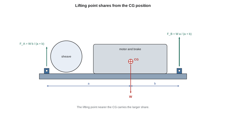
Many elevator loads are lifted from two points, either with two slings to one hook or with two hoists. Once the centre of gravity is known, the share of the weight at each point follows from a moment balance. If the centre of gravity is a distance a from point A and b from point B, the point nearer the centre of gravity carries more of the load.
The consequence surprises apprentices. A load whose centre of gravity is a quarter of the way along its length puts three quarters of its weight on the nearer lifting point. Two hoists, each rated for a little more than half the load, are not enough for such a lift, even though their combined rating is greater than the weight. The same applies to two legs of a sling to one hook: if the legs are the same length, the load tilts until it balances, and if they are adjusted to keep the load level, the leg nearer the centre of gravity carries more.
The Quayside machine is the case Tamsin worked through. The manual gives the machine weight and the position of its centre of gravity from the sheave end, and the bedplate it is lifted with adds a uniform weight. The lifting points are lugs near each end of the bedplate. The code below finds the combined centre of gravity and the load at each lug.
# Quayside MRL machine on its bedplate: centre of gravity and lug loads
# positions measured from the sheave end of the bedplate (m)
parts = [  # (name, weight kg, position of its centre of gravity)
    ("machine", 600, 0.62),
    ("bedplate", 90, 0.50),
]
lug_a, lug_b = 0.08, 0.92         # positions of the two lifting lugs
W = sum(w for _, w, _ in parts)
xg = sum(w * x for _, w, x in parts) / W
a, b = xg - lug_a, lug_b - xg
FA, FB = W * b / (a + b), W * a / (a + b)
print(f"total weight {W} kg, centre of gravity at {xg:.3f} m from the sheave end")
print(f"lug A (sheave end): {FA:.0f} kg  = {100 * FA / W:.0f} %")
print(f"lug B (motor end): {FB:.0f} kg = {100 * FB / W:.0f} %")total weight 690 kg, centre of gravity at 0.604 m from the sheave end lug A (sheave end): 259 kg = 38 % lug B (motor end): 431 kg = 62 %
The centre of gravity lies past the middle of the bedplate, toward the motor, so the motor-end lug carries roughly three fifths of the weight. If the machine were lifted with two equal sling legs to one hook, the hook would be pulled toward the motor end, and the load would hang tilted until it balanced, which is not acceptable when it has to land on its support level. Ray's rigging for the lift, worked out in Lesson 8, uses legs of unequal length or an adjustable leg so that the hook sits over the centre of gravity and the machine stays level.
Finding the centre of gravity on site
When no document gives the centre of gravity, it can be found in the field. For a load that can be lifted a little, the rigger makes a trial lift: the load is raised just clear of its supports and the tilt is observed. If one end rises first, the hook is on that side of the centre of gravity, and the rigging is adjusted toward the other end and the trial repeated. The load is never lifted more than a few centimetres during a trial, and nobody puts a hand or foot under it.
A second method uses the weights at each end. If the load can be weighed at one end with a load cell while the other end rests on a support, then lifted at the other end the same way, the two readings give the share at each end and the centre of gravity follows from the moment balance. This is how Tamsin confirmed the centre of gravity of an old hydraulic power unit at Holloway Memorial Hospital before it was lifted out of its room.
Some loads have a centre of gravity that moves. A tank with liquid in it shifts its weight as it tilts, which is why oil is drained from power units and gear cases before they are lifted. A load with loose parts, such as a crate of brackets or a cab panel bundle, can shift inside its packing. And a load that is hinged or articulated, such as an escalator truss section with a loose handrail assembly, changes shape as it is lifted. These loads are emptied, secured or braced before the lift.
Height of the centre of gravity and stability
The height of the centre of gravity matters when a load is lifted from below its centre, as with a basket hitch under a tall load, or when it rests on rollers, skates or cribbing. A load with a high centre of gravity on a narrow base tips easily, and a load lifted from points below its centre of gravity is unstable: if it tilts, the centre of gravity moves away from below the hook and the tilt grows. Tall loads are therefore lifted from points above their centre of gravity, such as lifting lugs at the top of a power unit frame, or are held upright by slings arranged so that the load cannot roll out of them. A controller cabinet, for example, is tall and narrow with its heavy transformer near the bottom; it is lifted from its top lifting eyes and moved upright, never laid on its side on a dolly.
Common mistakes
MistakeTaking a packing list weight as the weight of the part.
InsteadCheck what the weight includes; it may be a crate, a pallet or a different part.
MistakeForgetting the oil in a gear case or tank.
InsteadDrain liquids before the lift or include their weight and allow for their movement.
MistakeSizing two hoists for half the load each.
InsteadFind the centre of gravity; the nearer point can carry most of the weight.
MistakeLeaving out the rigging weight.
InsteadAdd slings, shackles, spreaders and clamps to the load weight.
MistakeMaking a trial lift high enough to reach under the load.
InsteadLift a few centimetres only, observe the tilt, and lower to adjust.
Summary and key terms
- The weight comes first from manufacturer documents, then from weighing, and otherwise from dimensions and density.
- Calculated weights are rounded up with a margin, and the rigging weight is added.
- A freely hanging load turns until its centre of gravity is below the hook.
- The centre of gravity of a composite load is the weighted average of the positions of its parts.
- With two lifting points, the share at each point is inversely proportional to its distance from the centre of gravity.
- Liquids, loose parts and hinged sections make the centre of gravity move, and are drained, secured or braced first.
- Centre of gravity
- The point at which the whole weight of a load can be considered to act.
- Density
- Mass per unit volume of a material, used to estimate weight from dimensions.
- Trial lift
- Raising a load just clear of its supports to check its weight and balance before the full lift.
- Load cell
- An instrument hung in the rigging that measures the weight on it.
- Moment
- A force multiplied by its distance from a point, which tends to turn a load about that point.
- Rigging weight
- The weight of all the gear between the load and the hook.
Practice problems
Work each problem on paper first, then reveal the answer to check.
A steel plate is 2.0 m by 1.0 m by 20 mm. What does it weigh?
Show answer
2.0 × 1.0 × 0.020 × 7,850 = 314 kg.
A 900 kg load has its centre of gravity 0.3 m from lifting point A and 0.6 m from point B. What does each point carry?
Show answer
A carries 900 × 0.6 / 0.9 = 600 kg; B carries 300 kg.
Why is oil drained from a gear case before it is lifted?
Show answer
It adds weight that may not be in the estimate, and it moves as the load tilts, shifting the centre of gravity.
How can you tell during a trial lift which side of the centre of gravity the hook is on?
Show answer
The end on the hook side rises first; move the rigging toward the other end.
Lesson quiz · 5 questions
Score 60% or more to complete this lesson.
Create a free account to save your progress, take quizzes and earn a certificate.