
ELV-130 · Lesson 11 of 12 · 19 min
Escalator trusses and heavy equipment moves
Not every heavy load an elevator mechanic moves goes up or down a hoistway. Escalators arrive as steel trusses the size of a bus, power units and controllers have to be moved across finished hospital floors, and old machines leave buildings through loading docks and corridors. These moves use the same rigging as a hoistway lift, plus three more tools: skates that roll a load across a floor, jacks and cribbing that raise and lower it in small steps, and pulling hoists that move it under control. This lesson follows the replacement of one of the eight escalators at Brackenridge Centre and a smaller move at Holloway Memorial Hospital.
The Brackenridge escalator replacement
The escalator being replaced runs from the lower mall to the main level, a rise of 5.5 m (18 ft) at 30 degrees. The old unit is being removed in pieces, cut up in place after its steps, handrails and machinery are stripped out. The new unit arrives in two truss sections that are joined in the wellway, the opening in the floor where the escalator sits. The sections are long, heavy and fragile in their own way: a truss is stiff along its length when it is supported at its ends as designed, but it can twist or be dented if it is supported or lifted anywhere else. The manufacturer's installation manual gives the weight and centre of gravity of each section, the lifting points, and the points where it may and may not be supported.
| Item | Value | Note |
|---|---|---|
| Upper truss section | 4,200 kg (9,300 lb) | With the drive machine fitted at the factory |
| Lower truss section | 3,800 kg (8,400 lb) | With the tension carriage |
| Section length | about 7 m (about 23 ft) | Each, as delivered |
| Route | Loading dock, service corridor, lower mall floor, wellway | Night work, 22:00 to 06:00 |
| Lifting points | Engineered points in the main level structure above the wellway | Confirmed by the mall's engineer |
The move happens over three nights. On the first, the sections come off the delivery trucks at the loading dock with a forklift rated for them and are set on skates. On the second, they are rolled along the service corridor and across the lower mall floor to the foot of the wellway. On the third, they are lifted into the wellway with chain hoists from the engineered points above, joined, and set on their supports at the upper and lower floor edges with jacks and cribbing for the final adjustment. Each night ends with the load on cribbing or skates chocked in a barricaded area, and the mall opens in the morning around it.
Moving on skates
Machinery skates, also called load rollers or dollies, are low steel frames with rows of hardened rollers that carry a load across a floor. Each skate is rated for a load, and a set of four or more carries a heavy item with the load spread between them. A load on skates moves with a small fraction of its weight as the pulling force, which is what makes it possible to move a truss section with a hand-operated pulling hoist. That same ease means a load on skates on a slight slope can start rolling by itself, so a load on skates is always connected to something that controls it, and chocked when it stops.
Skates are placed under the load at its designed support points, which for an escalator truss are at or near its ends, where its bearing angles are, not at mid-span where the bottom chord could be dented. The truss rests on timber or steel cribbing on top of the skates so that it bears on a flat surface. Swivel skates at one end and fixed skates at the other let the load be steered, and the steering is done with the skate handles or with a pulling hoist at an angle, never by people pushing on the load from the side where they could be caught between it and a wall.
The force needed to pull a load on skates depends on the rolling resistance of the skates on that floor, which is a small fraction of the weight on smooth concrete and more on plywood or tile, and on any slope. On a slope, the component of the weight along the slope is added when moving uphill and has to be held back when moving downhill. The Brackenridge service corridor has a short ramp down from the loading dock to the mall level, which is the part of the route that needs most care.
# Pulling force on skates: level floor and the ramp from the loading dock
import math
W = 4400              # heavier truss section with cribbing (kg)
skates, skate_rating = 4, 2000   # number of skates and the rating of each (kg)
mu = {"smooth concrete": 0.02, "plywood over tile": 0.04}   # rolling resistance (illustrative)
ramp = math.degrees(math.atan(0.30 / 6.0))             # ramp from rise over run
hoist_rating = 1600  # wire rope pulling hoist (kg)
share = W / 2 / 2 * 1.5   # two ends, two skates per end, 50 % allowance for uneven bearing
print(f"skate load about {share:.0f} kg each against a rating of {skate_rating}: {'ok' if share <= skate_rating else 'NOT OK'}")
for surface, m in mu.items():
    for slope in (0.0, ramp):
        t = math.radians(slope)
        up = W * (m * math.cos(t) + math.sin(t))
        down = W * (math.sin(t) - m * math.cos(t))   # holding force needed going down
        print(f"{surface:<17} slope {slope:3.1f} deg: pull uphill {up:5.0f} kg, hold downhill {max(down, 0):5.0f} kg")
print(f"pulling hoist rated {hoist_rating} kg")skate load about 1650 kg each against a rating of 2000: ok smooth concrete slope 0.0 deg: pull uphill 88 kg, hold downhill 0 kg smooth concrete slope 2.9 deg: pull uphill 308 kg, hold downhill 132 kg plywood over tile slope 0.0 deg: pull uphill 176 kg, hold downhill 0 kg plywood over tile slope 2.9 deg: pull uphill 396 kg, hold downhill 44 kg pulling hoist rated 1600 kg
On the level, the pull is tiny: about the weight of a person to move a section that weighs as much as a small truck. On the ramp, the slope adds far more than the rolling resistance, and going down the smooth concrete ramp, the load wants to roll by itself with a force greater than the whole level pull. On plywood the holding force is smaller, but it is still there, and it changes as the surface changes under the skates. That is why the ramp is the one place where the section is moved downhill with a pulling hoist holding it back from an anchor at the top of the ramp, a second pulling hoist ready on the downhill side, and chocks carried alongside each skate by a person walking beside the load, not in front of it. The skate load includes an allowance for uneven bearing, because a truss on a floor that is not perfectly flat does not share its load evenly between four skates.
The floor itself has to carry the skates. Four skates under a section concentrate its whole weight on a few small contact areas, which is a far harsher load on a floor than the finished escalator, which bears on its end supports. The route across the lower mall was walked with the mall's engineer, who confirmed the floor's capacity, required steel plates over the expansion joints and a trench drain cover, and required plywood under the skates on the tiled areas to protect the tile. Plywood increases the rolling resistance, which the code above shows, and it is laid in a continuous track with the joints staggered so that a skate does not drop into a gap.
Lifting into the wellway
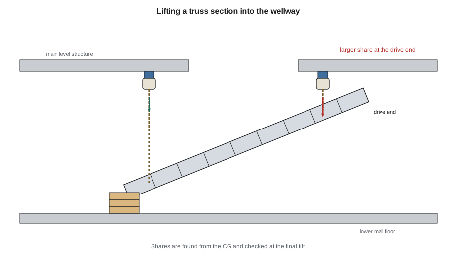
At the foot of the wellway, each section is lifted with two chain hoists hung from the engineered lifting points in the main-level structure above, one near each end, using the lifting points on the truss that the manual shows. The share at each end is found from the centre of gravity, as Lesson 2 showed, and the upper section, with the drive machine at its upper end, puts much more of its weight on the upper hoist. Each hoist and lifting point is checked for its own share, not half the weight. The section is raised until it is clear of its skates, the skates are removed, and it is lifted and tilted to the escalator's angle by raising one hoist more than the other, in small steps, with both hoists working under one signal person.
Tilting a load between two hoists changes the share each one carries, because the centre of gravity moves horizontally relative to the lifting points as the load tilts. For a truss whose lifting points are near its top chord, the change is small. The plan for Brackenridge checked the shares at the final 30-degree angle, and the upper hoist's share at that angle governed the choice of hoist. A long load being tilted is also watched along its whole length for contact with the wellway edges, which are protected with timber.
Joining and setting the truss
The two sections are joined in the wellway at the splice the manufacturer designed, with the splice plates and bolts torqued to the manual's values. During joining, both sections are supported, either on the hoists with their loads checked or on cribbing under the splice at the designed support points. Nobody works under a section that is hanging from hoists; the splice bolting is done from the side or from above with the sections on cribbing.
Setting the joined truss on its supports is done with jacks and cribbing. Each end of the truss bears on a support angle or bracket on the edge of the floor structure, through bearing plates and, often, isolation pads. The final position, level across the width, and the height of each end are set by jacking each end up a little at a time, adjusting the shims, and lowering it onto the bearing. Lesson 7's rules apply: one jack at a time on a load supported at several points, the cribbing following the load within one layer, the jack on a firm base under a designed jacking point, and nobody under the truss while it is on a jack.
# Jacking one end of the truss to its bearing with the cribbing following
target = 0.30          # height to raise the end above its present support (m)
stroke = 0.075          # usable jack stroke per lift (m)
layer = 0.10           # timber thickness added to the crib per layer (m)
h = crib = 0.0
step = 0
while h < target - 1e-9:
    lift = min(stroke, target - h)
    h += lift
    step += 1
    while crib + layer <= h + 1e-9:     # add layers as soon as there is room
        crib += layer
    gap = max(h - crib, 0.0)
    print(f"lift {step}: end at {h:.3f} m, crib at {crib:.3f} m, gap {gap:.3f} m (shims and wedges)")
print("lower onto the crib after each lift; the gap never exceeds one layer")lift 1: end at 0.075 m, crib at 0.000 m, gap 0.075 m (shims and wedges) lift 2: end at 0.150 m, crib at 0.100 m, gap 0.050 m (shims and wedges) lift 3: end at 0.225 m, crib at 0.200 m, gap 0.025 m (shims and wedges) lift 4: end at 0.300 m, crib at 0.300 m, gap 0.000 m (shims and wedges) lower onto the crib after each lift; the gap never exceeds one layer
The jack's usable stroke is shorter than a crib layer, so after some lifts there is not yet room for another layer, and the gap is filled with hardwood shims and wedge pairs before the jack is released. The rule that the gap never exceeds one layer means that if the jack slipped at any point, the truss would drop only onto the crib a short distance below. Each end is raised alternately, so that the truss is never more than a small amount out of level, and the opposite end is chocked so that the truss cannot slide off its bearing as it tilts.
A smaller move at the hospital
At Holloway Memorial Hospital, the new hydraulic power unit for car 2 has to travel from the loading dock to the machine room in the basement, through a corridor that stays in use by the hospital, past an imaging department and through two sets of fire doors. The power unit weighs 460 kg (1,000 lb) empty, and it is moved on a four-wheel equipment dolly with its tank empty, upright, strapped to the dolly, by two mechanics walking beside it, with a third ahead clearing the way. The route was agreed with the hospital's facilities department, the move is done on the night window, the floor is protected with hardboard, and the infection control rules for the corridor are followed. The lift onto its pad in the machine room is the one checked in Lesson 4.
A small move like this has its own hazards: a dolly that runs away on a slight slope, a tall load that tips when a wheel catches a door threshold, and people in the corridor who do not know a heavy load is coming. The controls are the same as for the truss in miniature: a known weight and centre of gravity, a load secured to its dolly, the slope checked, the route walked in advance, a spotter ahead, and nobody in front of the load on a slope.
Old equipment leaving the building
Removing old equipment is often harder than installing new equipment, because nobody knows its exact weight, its lifting points may be corroded or missing, and it may have to be cut into pieces that each have to be rigged. Old escalator trusses are usually cut in the wellway into pieces small enough to handle, each piece rigged as it is cut, with the cutting planned so that no piece is left hanging from a partly cut section. Old machines and motor-generator sets are drained, their weights estimated as in Lesson 2, and their lifting points checked or replaced with designed attachments. And each piece leaves on a route planned as carefully as the route in.
Common mistakes
MistakePlacing skates under the middle of a truss.
InsteadSupport the truss only at the points the manual allows, usually at its ends.
MistakeMoving a load on skates down a ramp without a holdback.
InsteadControl it with a pulling hoist from an anchor above, with chocks walked alongside.
MistakeAssuming two hoists on a truss each carry half the weight.
InsteadFind each share from the centre of gravity and check it at the final tilt.
MistakeLetting the cribbing fall behind a jacked truss end.
InsteadAdd layers and shims after every lift; the gap never exceeds one layer.
MistakePushing a load sideways by hand to steer it.
InsteadSteer with skate handles or a pulling hoist, never from between the load and a wall.
Summary and key terms
- Heavy moves use skates, jacks, cribbing and pulling hoists as well as slings and hoists.
- Skates carry a load at its designed support points and are always controlled and chocked.
- The pull on skates is W(μ cos θ + sin θ); slopes dominate, and downhill moves need a holdback.
- Floors under skates need confirmed capacity and protection.
- Two-hoist lifts of long loads check each share from the centre of gravity at the final tilt.
- Jacking proceeds in small lifts with the cribbing following, one end at a time.
- Machinery skate
- A low steel frame with rollers that carries a heavy load across a floor.
- Rolling resistance
- The force needed to keep a load rolling, as a fraction of its weight.
- Wellway
- The opening in a floor in which an escalator is installed.
- Truss
- The steel structure of an escalator that carries the steps, track and machinery.
- Holdback
- A hoist or line that restrains a load from moving faster than intended, especially downhill.
- Bearing angle
- The steel support at each end of an escalator truss that rests on the building structure.
Practice problems
Work each problem on paper first, then reveal the answer to check.
A 4,000 kg load on skates has a rolling resistance of 0.03 on a level floor. What pull is needed?
Show answer
About 120 kg-force.
The same load is on a 3-degree ramp. About what force does it exert down the slope?
Show answer
4,000 × sin 3° = about 209 kg-force, before rolling resistance.
Why are truss ends jacked alternately?
Show answer
To keep the truss close to level so it cannot slide or twist on its supports.
What fills the gap between the crib and a jacked load when there is not room for another layer?
Show answer
Hardwood shims and wedge pairs.
Lesson quiz · 5 questions
Score 60% or more to complete this lesson.
Create a free account to save your progress, take quizzes and earn a certificate.