
ELE-499 · Lesson 7 of 12 · 22 min
Embedded control and communications
Mateo owned the parts of the project that think: the site energy controller that coordinates the canopy, and the firmware inside the demonstrator's converter. They work on very different time scales. The converter's current loops act every 50 microseconds; the site controller decides charging setpoints every second and plans the night every fifteen minutes; and the reports to Larchmont's SCADA arrive every few seconds. This lesson covers how Mateo divided the control into layers, how the site controller shares power among vehicles, how the converter's inner loop was designed and tested, how the devices talk to each other, and how the system is protected against both failures and attackers.
Control in layers
Mateo used a layered structure that is common in power and energy systems. The fastest layer is device control: the converter's current and voltage loops, the inverter's own internal controls and the chargers' current regulation. These run inside each device and keep it stable and within its ratings regardless of what higher layers ask. The middle layer is site coordination: the site energy controller reads measurements, decides how much power each device should take or deliver, and sends setpoints. The top layer is planning and supervision: forecasting the night's energy, choosing the storm-reserve mode, and reporting to people and to Larchmont's systems.
The rule that makes layers safe is that each lower layer protects itself. If the site controller sends a nonsensical setpoint, the charger must still refuse to exceed its rating, and the inverter must still respect the battery management system's limits. A higher layer can make the system work well; it must never be the only thing that keeps it safe.
The site controller's modes
The site controller is written as a state machine with a small number of well-defined modes. In normal mode it manages charging to meet departure times within the grid limit, uses the battery to shave the evening peak and stores surplus solar. In storm-ready mode, which Larchmont's operations centre can select remotely or the controller enters automatically from November to March, it holds the battery above its 70 % reserve and gives the two line trucks priority. In islanded mode, entered when the utility supply fails, the hybrid inverter forms its own AC supply for the canopy panel, the fast charger is disabled, and only the Level 2 chargers for storm-priority vehicles are enabled. In fault mode, any unexplained condition causes the controller to command safe setpoints and raise an alarm. Every transition between modes is logged with its cause.
Writing the controller as a state machine has practical benefits. Each mode's behaviour can be tested separately; the allowed transitions are explicit, so the controller cannot drift into an undefined state; and the log of transitions gives the operations staff a clear account of what happened during an incident.
Sharing power among vehicles
The heart of normal and storm-ready modes is the charging allocator. Every second it takes the power available, which is the grid limit plus solar output plus whatever the battery may contribute above its floor, and divides it among the connected vehicles. Mateo's first version simply divided power equally, which failed the client's real need: on a storm night, the line trucks must be ready first. The version below sorts sessions by priority, storm trucks first and then by hours left before departure, and gives each the rate it needs to finish on time, up to its charger's limit, until the available power runs out.
# Site energy controller: allocate charging power under the grid cap, then step-test the battery current loop
GRID_MAX = 60.0
def allocate(t, pv, batt_avail, sessions):
    """Share available power by priority: storm-ready trucks first, then by hours left before departure."""
    avail = min(GRID_MAX + pv + batt_avail, 1e9)
    need = sorted(sessions, key=lambda s: (not s['storm'], s['depart'] - t))
    out = {}
    for s in need:
        p = min(s['max_kw'], s['kwh_left'] / max(s['depart'] - t, 0.25), avail)
        out[s['id']] = round(p, 1); avail -= p
    return out
sessions = [  # (id, storm-priority truck, departure hour, kWh still needed, charger limit kW)
    ('truck 41', True, 6.5, 59, 10.0), ('truck 42', True, 6.5, 50, 10.0), ('bucket 17', False, 7.0, 50, 60.0),
    ('van 8', False, 6.0, 48, 10.0), ('van 9', False, 6.0, 45, 10.0), ('pickup 23', False, 7.0, 29, 10.0),
    ('pickup 24', False, 7.0, 26, 10.0), ('pickup 25', False, 7.5, 21, 10.0)]
def snapshot(t, pv, batt, scale):
    ss = [{'id': i, 'storm': s, 'depart': d + 24, 'kwh_left': k * scale, 'max_kw': m} for i, s, d, k, m in sessions]
    a = allocate(t + (24 if t < 12 else 0), pv, batt, ss)
    print(f"{t:05.2f} h, battery {batt:.0f} kW available: " + ', '.join(f'{k} {v}' for k, v in a.items()) + f"; total {sum(a.values()):.1f} kW")
snapshot(18.0, 0.0, 40.0, 1.0)          # a normal evening
snapshot(2.0, 0.0, 0.0, 1.6)            # after a storm call-out: late arrivals, battery held at its reserve floor
# discrete PI current loop for the battery converter, sampled at 20 kHz; plant: L = 200 uH (two phases in parallel)
L, R, VDC, TS = 200e-6, 0.03, 400.0, 1 / 20e3
KP, KI = 0.012, 25.0                    # duty per amp, duty per amp-second
i = integ = 0.0; ref = 20.0; out = []
for k in range(200):
    if k == 40: ref = 29.0              # step from 4.1 kW to 6 kW
    e = ref - i; integ += e * TS
    d = max(-0.95, min(0.95, KP * e + KI * integ))
    v_l = d * VDC * 0.5 - R * i         # simplified averaged model around the operating point
    i += v_l / L * TS; out.append(i)
step = out[40:]
overshoot = (max(step) - 29.0) / 9.0 * 100
settle = next(k for k in range(len(step)) if all(abs(x - 29.0) < 0.02 * 29.0 for x in step[k:])) * TS * 1e3
print(f"current step 20 -> 29 A: overshoot {overshoot:.1f} %, 2 % settling {settle:.2f} ms")18.00 h, battery 40 kW available: truck 41 4.7, truck 42 4.0, van 8 4.0, van 9 3.8, bucket 17 3.8, pickup 23 2.2, pickup 24 2.0, pickup 25 1.6; total 26.1 kW 02.00 h, battery 0 kW available: truck 41 10.0, truck 42 10.0, van 8 10.0, van 9 10.0, bucket 17 16.0, pickup 23 4.0, pickup 24 0.0, pickup 25 0.0; total 60.0 kW current step 20 -> 29 A: overshoot 11.1 %, 2 % settling 0.55 ms
On a normal evening, with the battery able to contribute 40 kW, every vehicle gets the modest rate it needs, and total demand is only 26 kW, well inside the limits. The second case is the one the supervisors described: after a storm call-out the vehicles arrive late needing more energy, and the battery is held at its reserve floor, so only the 60 kW from the grid is available. The two line trucks and the vans get their full 10 kW, the bucket truck gets what remains on the fast charger, and two pickups are paused until power frees up. The client agreed that this was exactly the behaviour they wanted.
A real allocator needs more than this. It recomputes every second as vehicles connect, finish or change their reported state of charge; it ramps setpoints rather than stepping them, so that the inverter and battery are not hit with sudden load changes; it keeps a margin of a few kilowatts below the limit so that measurement error and the delay before chargers respond cannot push the site over it; and it never sets a charger below the minimum current that the charging standard allows, pausing the session instead.
The converter's current loop
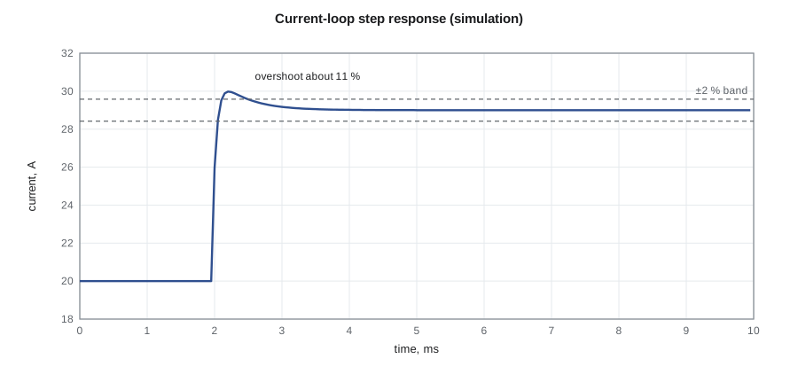
Inside the demonstrator, a digital signal controller runs each phase's current loop at 20 kHz. Mateo designed it with the methods from ELE-390: a model of the plant, here the inductor and its winding resistance driven by the switched voltage; a proportional-integral (PI) controller; and a check of the closed-loop response. The second part of the program simulates the averaged loop and applies a step in the current reference from 20 A to 29 A, equivalent to raising battery power from about 4.1 kW to 6 kW.
The response overshoots by about 11 % and settles to within 2 % in about half a millisecond. Mateo's target, derived from the need for the outer voltage loop to be at least ten times slower, was settling within one millisecond with overshoot below 20 %, so the design met it. He also checked the loop at the battery's lowest and highest voltages, because the plant gain changes with operating point, and confirmed that the controller's output limits and anti-windup behaved properly when the reference was stepped beyond the current limit.
Worked problem
Loop speed separation
The current loop settles in 0.55 ms. If the outer bus-voltage loop should be at least ten times slower, what is the fastest settling time it should be designed for?
Show solution
- Ten times slower than 0.55 ms is 5.5 ms.
- Choosing about 10 ms gives margin for parameter variation.
Answer: At least about 5.5 ms; the team designed the voltage loop to settle in about 10 ms.
Talking to the devices
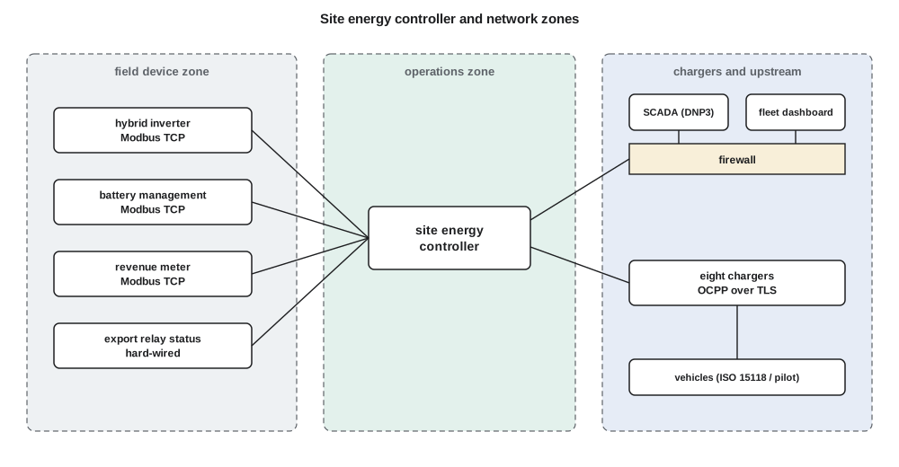
The site controller speaks several protocols, each standard in its own world. To the hybrid inverter, the battery management system and the meter, it uses Modbus TCP, a simple register-based protocol carried over Ethernet, using the vendors' published register maps; many distributed energy devices follow the SunSpec information models, which standardize the meaning of the registers. To the chargers it uses the Open Charge Point Protocol (OCPP), the open standard maintained by the Open Charge Alliance for communication between chargers and a charging management system. OCPP version 2.0.1 is widely deployed, and version 2.1 has been published by the IEC as IEC 63584-210. Through OCPP's smart charging profiles the controller can set a power limit on each charger, start and stop sessions, and receive meter values and status.
Between the charger and the vehicle, the charging standard's basic pilot signal tells the vehicle how much current it may draw; chargers and vehicles that support ISO 15118 can also exchange the vehicle's state of charge and departure time, which the allocator uses when available. To Larchmont's SCADA, the controller presents a small set of points using DNP3, the protocol most North American utilities use for their supervisory systems: site import power, battery state of charge, mode, alarms and a remote storm-ready command.
For each link, Mateo wrote down the update rate, the timeout and the fallback behaviour defined in the interface document. If a charger loses contact with the controller for 60 seconds it falls back to a preset safe current. If the controller loses the meter reading, it cannot see the grid import, so it immediately reduces all chargers to their safe currents and raises an alarm. If the link to SCADA fails, the site keeps running in its current mode and buffers its data.
Cybersecurity
A controller that can switch eight chargers and a 100 kW battery, and that connects to a utility's SCADA system, must be protected against deliberate misuse as well as accidents. The team's approach followed the defensive practices described in industrial control system security standards such as the IEC 62443 series, scaled to a small site. The field devices sit on their own network segment, separated from the corporate network and the internet by a firewall that allows only the specific connections the system needs. Every default password was changed, and the controller has no shared accounts. OCPP traffic uses Transport Layer Security with certificates, one of the security profiles the protocol defines, so that chargers and controller authenticate each other. Firmware updates for the controller must be signed, and the controller logs every configuration change and remote command.
Physical safety does not depend on the network. The zero-export relay, the breakers and each device's own protections work whether or not the controller or its network is healthy, so that a compromised or failed controller can make the system inefficient but cannot make it unsafe. Larchmont's security team reviewed the design at the CDR, and the team followed their requirements for remote access, which is permitted only through the utility's own managed connection.
Testing software as it is written
Mateo wrote the allocator and mode logic so that they could be tested without hardware. Each function takes measurements and returns setpoints, and a set of automated tests checks its behaviour in dozens of cases: a vehicle connecting with a nearly full battery, a storm declared in the middle of the night, the meter reading going stale, two vehicles with the same departure time, the battery at its floor. The tests run every time the code changes. Hardware-in-the-loop tests, where the real controller drives simulated chargers and an emulated inverter, came next, and lesson 10 describes the full system tests.
Common mistakes
MistakeMaking the site controller the only thing that keeps devices within limits.
InsteadEach device must protect itself; higher layers improve performance, not safety.
MistakeLeaving fallback behaviour on communication loss undefined.
InsteadSpecify timeouts and safe fallback setpoints for every link.
MistakeRunning the allocator right at the grid limit.
InsteadKeep a margin for measurement error and charger response delay.
MistakeLeaving default passwords and flat networks in place.
InsteadSegment the network, change defaults, use authenticated encrypted protocols and signed firmware.
Summary and key terms
- Control is layered: device loops, site coordination, and planning and supervision.
- Each lower layer protects itself regardless of higher-layer commands.
- A state machine with defined modes makes behaviour testable and auditable.
- The allocator shares available power by priority and departure time within the grid limit.
- The converter's PI current loop settles in about 0.55 ms, at least ten times faster than the voltage loop.
- Modbus TCP, OCPP and DNP3 connect the controller to devices, chargers and SCADA, each with defined fallbacks.
- Network segmentation, authenticated encrypted links, changed defaults and signed firmware protect the system.
- State machine
- Software organized as a set of defined modes with explicit transitions.
- Charging allocator
- The algorithm that divides available power among charging vehicles.
- PI controller
- A controller whose output is proportional to the error plus its integral.
- Modbus TCP
- A simple register-based industrial protocol carried over Ethernet.
- OCPP
- The Open Charge Point Protocol between chargers and a charging management system.
- DNP3
- A protocol widely used for utility supervisory control and data acquisition.
- Network segmentation
- Dividing a network into zones with controlled connections between them.
Practice problems
Work each problem on paper first, then reveal the answer to check.
Why does each charger fall back to a safe current on loss of communication?
Show answer
So that the site stays within its grid limit and vehicles still charge if the controller fails.
In the storm case, why are two pickups paused?
Show answer
Only 60 kW is available and higher-priority vehicles use it first.
Why should the allocator keep a margin below the grid limit?
Show answer
Measurement error and charger response delay could otherwise push the site over the limit.
Why is the outer voltage loop designed to be much slower than the current loop?
Show answer
So that the loops do not interact and the inner loop can be treated as ideal.
Name two protocols the controller uses and what they connect.
Show answer
Modbus TCP to the inverter, battery and meter; OCPP to the chargers; DNP3 to SCADA.
Why must physical safety not depend on the network?
Show answer
A failed or compromised controller must not be able to make the system unsafe.
Lesson quiz · 5 questions
Score 60% or more to complete this lesson.
Create a free account to save your progress, take quizzes and earn a certificate.