
ELE-350 · Lesson 2 of 12 · 24 min
Amplitude modulation
Amplitude modulation is the oldest way of putting a voice on a radio wave and still the simplest to understand. The carrier's amplitude follows the message, so the message can be seen directly in the outline of the waveform on an oscilloscope. Medium-wave broadcasting, aircraft voice radio and many measurement systems use it today, and its suppressed-carrier and single-sideband forms are the building blocks of every digital radio's quadrature modulator. This lesson develops double-sideband suppressed-carrier modulation, conventional AM with a carrier, the envelope detector, single sideband and the quadrature idea that leads to QAM.
The topic arrives at Cedarline in an unexpected way. Leo installs the first APS-2 prototype on a test pole in the yard and hears a faint talk show mixed in with the locator tick. A medium-wave broadcast station's tower stands a few kilometres away, and its strong field induces a radio-frequency voltage on the 15 m microphone cable. Somewhere in the preamplifier a transistor junction acts as a crude detector and recovers the programme. Understanding why this happens, and why the fix is a small capacitor at the input, requires understanding how AM works and how it is demodulated.
Double-sideband suppressed-carrier modulation
The most direct way to shift a message to a carrier frequency is to multiply them. With a message m(t) of bandwidth W and a carrier at f_c much larger than W, the product is a double-sideband suppressed-carrier (DSB-SC) signal. By the modulation theorem its spectrum is the message spectrum shifted to ±f_c. The part above f_c is the upper sideband and the part below is the lower sideband, a mirror image. No discrete carrier component appears, which is why the carrier is called suppressed, and the transmission bandwidth is 2W.
The multiplier can be an analog multiplier chip, a balanced mixer of diodes, or a switching modulator that reverses the polarity of the message at the carrier rate and then filters the result. A switching modulator multiplies by a square wave rather than a cosine, so it creates copies of the spectrum at f_c, 3f_c, 5f_c and so on; a band-pass filter at f_c keeps only the wanted one.
Coherent demodulation
To recover the message, the receiver multiplies the received signal by a local copy of the carrier and low-pass filters the result. If the local oscillator has the right frequency but a phase error φ, the product contains the message scaled by cos φ plus a component at 2f_c that the filter removes.
This is synchronous or coherent detection, and its weakness is obvious from the result. A phase error of 60° halves the output, and 90° removes it completely. A small frequency error Δf makes φ rotate, so the output beats up and down at Δf. The receiver therefore needs a carrier recovery circuit, such as a Costas loop, which uses two branches in quadrature and a phase-locked loop to lock the local oscillator to the suppressed carrier. Digital receivers solve the same problem for PSK and QAM, as lesson 9 explains.
Conventional AM
Adding a large carrier to the DSB-SC signal makes the receiver much simpler. In conventional AM, the transmitted amplitude is A_c[1 + μ m_n(t)], where m_n(t) is the message normalized so that its largest magnitude is 1 and μ is the modulation index. As long as μ ≤ 1, the bracket never goes negative, and the envelope of the waveform is an exact, shifted copy of the message.
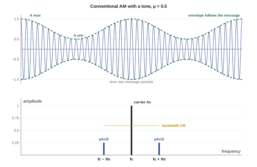
The modulation index is easy to measure on an oscilloscope from the largest and smallest envelope heights. If μ exceeds 1, the envelope crosses zero and the waveform is overmodulated; the envelope then no longer follows the message, the detector output is distorted, and the abrupt phase reversals spread energy far outside the channel. Broadcast transmitters use limiters and processors that keep negative peaks just short of 100 percent modulation while letting positive peaks go somewhat higher.
Power and efficiency
The price of the simple receiver is power. For a single tone, m_n(t) = cos(2πf_m t), the AM signal expands into a carrier and two sidebands of amplitude μA_c/2. The carrier carries no information at all, yet it takes most of the transmitted power. The power efficiency η is the fraction of the total power that is in the sidebands.
At 100 percent tone modulation the efficiency reaches only one third. Speech and music have a much higher ratio of peak to average power than a tone, so the average modulation in real programmes may be 30 percent or less, and the efficiency falls to a few percent. That is the main reason point-to-point voice radio moved to single sideband and frequency modulation, and why digital radios use suppressed-carrier formats.
Worked problem
Power in a broadcast transmitter
A transmitter has a carrier power of 1.0 kW and is modulated by a tone to μ = 0.8. Find the total power, the power in each sideband and the efficiency. Then find the efficiency if average programme modulation is μ = 0.3.
Show solution
- \[P_{SB,\,total} = P_c\frac{\mu^2}{2} = 1000 \times \frac{0.64}{2} = 320\ \text{W} \;(160\ \text{W per sideband})\]
- \[P_T = 1000 + 320 = 1320\ \text{W} \qquad \eta = \frac{0.64}{2.64} = 24.2\,\%\]
- \[\mu = 0.3:\quad \eta = \frac{0.09}{2.09} = 4.3\,\%\]
Answer: Even at 80 percent modulation, three quarters of the power is in the carrier. At typical programme levels, about 96 percent of the power does nothing but make the receiver simple.
The envelope detector
The envelope detector is a diode followed by a resistor and capacitor in parallel. On each positive carrier peak the diode conducts and charges the capacitor to the peak voltage; between peaks the diode is off and the capacitor discharges slowly through the resistor. The output rides along the peaks, tracing the envelope with a small sawtooth ripple at the carrier frequency that a following low-pass filter removes. The time constant RC must satisfy two conflicting conditions. It must be long compared with the carrier period, so that the capacitor holds the voltage between peaks, and short compared with the message period, so that the output can fall as fast as the envelope does.
If RC is too long, the output cannot follow the falling edge of the envelope and cuts across it in straight exponential lines, a distortion called diagonal clipping. If RC is too short, the ripple is large. The second condition above, derived by requiring that the exponential decay be at least as steep as the envelope at every point, is the precise limit for a single tone. The detector cannot work on DSB-SC, because the envelope of a DSB-SC signal is |m(t)|, not m(t); the phase reversals at each zero crossing of the message are lost.
The same physics explains Leo's talk show. Any nonlinear junction driven by a large RF voltage acts as a detector: the base-emitter junction of the preamplifier's first transistor rectified the induced broadcast signal, and the junction capacitance and bias resistors formed a crude RC filter. The cure is to keep the RF out of the junction, with a small capacitor from each input to the shield at the connector and a series resistor, forming a low-pass filter well above the voice band. ELE-340 added exactly such a filter of 1 kΩ and 1 nF for this reason, with a corner near 159 kHz; a stronger station may need a ferrite bead as well.
import math
fs, fc, fm, Ac, mu = 400e3, 20e3, 1e3, 1.0, 0.5
N = 4000                     # 10 ms of signal: whole numbers of carrier and tone cycles
x = [Ac * (1 + mu * math.cos(2*math.pi*fm*n/fs)) * math.cos(2*math.pi*fc*n/fs) for n in range(N)]
def amplitude(f):            # single-frequency DFT, scaled to sinusoid amplitude
    re = sum(v * math.cos(2*math.pi*f*n/fs) for n, v in enumerate(x))
    im = sum(v * math.sin(2*math.pi*f*n/fs) for n, v in enumerate(x))
    return 2 * math.hypot(re, im) / N
for f in (fc - fm, fc, fc + fm, fc + 2*fm):
    print(f"{f/1e3:5.1f} kHz: amplitude {amplitude(f):.3f}")
for m in (0.3, 0.5, 0.8, 1.0):
    print(f"mu = {m:.1f}: efficiency = {100*m*m/(2+m*m):.1f} %")
# ideal-diode envelope detector with different RC values
env = [Ac * (1 + mu * math.cos(2*math.pi*fm*n/fs)) for n in range(N)]
rc_max = math.sqrt(1 - mu**2) / (mu * 2*math.pi*fm)
print(f"diagonal-clipping limit RC = {rc_max*1e6:.0f} us")
for RC in (20e-6, 150e-6, 1000e-6):
    v, err = 0.0, 0.0
    a = math.exp(-1 / (fs * RC))
    for n in range(N):
        v = max(x[n], v * a)          # diode conducts when input exceeds the capacitor voltage
        if n >= N // 2: err += (v - env[n]) ** 2
print(f"RC = {RC*1e6:6.0f} us: rms error = {math.sqrt(err/(N//2)):.3f}")19.0 kHz: amplitude 0.250 20.0 kHz: amplitude 1.000 21.0 kHz: amplitude 0.250 22.0 kHz: amplitude 0.000 mu = 0.3: efficiency = 4.3 % mu = 0.5: efficiency = 11.1 % mu = 0.8: efficiency = 24.2 % mu = 1.0: efficiency = 33.3 % diagonal-clipping limit RC = 276 us RC = 20 us: rms error = 0.580 RC = 150 us: rms error = 0.164 RC = 1000 us: rms error = 0.243
The spectrum shows the carrier at amplitude 1.000 and two sidebands of 0.250, exactly μA_c/2, with nothing at f_c + 2f_m. The detector results show the trade-off. With RC = 20 µs, only four carrier periods, the capacitor discharges almost completely between peaks and the error is largest. With 150 µs, inside both limits, the error is smallest. With 1 ms, far beyond the 276 µs diagonal-clipping limit, the output cannot follow the envelope down, and the error rises again to about one and a half times the best value.
Single sideband
Both sidebands of an AM or DSB-SC signal carry the same information, so one of them can be removed. Single-sideband (SSB) modulation transmits only the upper or the lower sideband. It halves the bandwidth to W and puts all the transmitted power into information. It is the standard for long-distance voice on high-frequency radio, both amateur and marine, and the same idea, applied to digital signals, is used in some cable and broadcast systems.
There are two classic ways to generate SSB. The filter method makes DSB-SC and removes one sideband with a sharp band-pass filter, often a crystal filter at a fixed intermediate frequency; it works well when the message has no content near zero frequency, like speech above 300 Hz, so there is a gap between the sidebands for the filter to use. The phasing method uses the formula above directly: m̂(t) is the Hilbert transform of the message, the message with every frequency component shifted by −90°. Two DSB-SC modulators driven by carriers in quadrature are summed, and one sideband cancels. Modern radios do the phasing method digitally, where a 90° shift across the whole audio band is easy to compute.
SSB has a cost: it must be demodulated coherently, and a small frequency error shifts every audio component by the same number of hertz. A 50 Hz error makes speech sound high or low pitched but remains intelligible, which is why SSB is acceptable for voice but needs very stable oscillators for data. Vestigial sideband (VSB) is a compromise that keeps one sideband and a gradual vestige of the other, so the filter need not be sharp; analog television and the North American digital television standard used it.
Quadrature amplitude modulation
The phasing equation hints at a more general idea. A cosine carrier and a sine carrier at the same frequency are orthogonal: over many cycles, their product averages to zero. Two independent messages can therefore be sent at once, one on each, in the bandwidth of one DSB signal, and a coherent receiver separates them by multiplying by cos and by sin. This is quadrature amplitude modulation. In analog form it carried the colour information in older television. In digital form, with each message taking a few discrete levels, it becomes the QAM of lesson 8, which carries most of the world's data.
| Scheme | Bandwidth | Power efficiency | Receiver | Typical use |
|---|---|---|---|---|
| Conventional AM | 2W | at most 33 %, often a few % | Envelope detector | Medium-wave broadcast, aircraft voice |
| DSB-SC | 2W | 100 % | Coherent, needs carrier recovery | Stereo FM subcarrier, modulators inside radios |
| SSB | W | 100 % | Coherent, stable oscillator | HF voice, marine and amateur radio |
| VSB | slightly more than W | high | Coherent | Television |
| Analog QAM | 2W for two messages | 100 % | Coherent, I and Q branches | Colour subcarrier; basis of digital QAM |
What this means for the TLR-1
The TLR-1 will not use analog AM, but Amara takes three lessons from the family for the design. A carrier that holds no information wastes the limited power the band allows, so suppressed-carrier formats are preferred. Coherent detection is more efficient but needs carrier recovery, which costs preamble time at the start of each short telemetry burst. And every radio front end must be protected from strong off-channel signals that a nonlinear junction can demodulate, exactly as the microphone preamplifier did.
Common mistakes
MistakeUsing an envelope detector on a DSB-SC signal.
InsteadThe envelope of DSB-SC is |m(t)|; DSB-SC needs coherent detection.
MistakeChoosing the envelope detector RC only to reduce ripple.
InsteadToo long a time constant causes diagonal clipping; keep RC below the limit set by the highest message frequency and modulation index.
MistakeExpecting AM power efficiency near 50 percent at full modulation.
InsteadFor a tone the maximum is one third, and real programmes average much less.
MistakeForgetting that a phase error scales a coherent detector's output by cos φ.
InsteadA 90° error removes the output completely; carrier recovery is essential.
Summary and key terms
- DSB-SC multiplies the message by the carrier, occupies 2W and needs coherent detection with carrier recovery.
- Conventional AM adds a carrier so the envelope follows the message when μ ≤ 1; overmodulation distorts it.
- AM power efficiency is μ²/(2 + μ²) for a tone, at most 33 percent.
- The envelope detector's time constant must lie between the carrier period and the limit set by diagonal clipping.
- SSB keeps one sideband, halving bandwidth; it is generated by filtering or by the phasing method with a Hilbert transform.
- Cosine and sine carriers are orthogonal, so two messages can share one band as QAM.
- Modulation index
- For AM, the ratio of the message amplitude to the carrier amplitude, μ, which sets the depth of modulation.
- Sideband
- The band of frequencies above or below the carrier produced by modulation.
- Envelope detector
- A diode and RC circuit whose output follows the peaks of an AM waveform.
- Coherent detection
- Demodulation by multiplying with a local carrier of the correct frequency and phase.
- Diagonal clipping
- Envelope detector distortion caused by a time constant too long to follow the falling envelope.
- Single sideband
- Amplitude modulation in which only one sideband is transmitted.
- Hilbert transform
- An operation that shifts every frequency component of a signal by 90 degrees.
Practice problems
Work each problem on paper first, then reveal the answer to check.
An AM waveform has envelope peaks of 9 V and troughs of 3 V. Find μ.
Show answer
μ = (9 − 3)/(9 + 3) = 0.5.
A 500 W carrier is modulated to μ = 1 by a tone. Find the total power and sideband power.
Show answer
Sidebands 250 W total; total 750 W.
A voice signal of 300–3400 Hz is sent by DSB-SC and by SSB. Give each bandwidth.
Show answer
DSB-SC: 6.8 kHz (strictly 2 × 3.4 kHz). SSB: 3.1 kHz, the 300–3400 Hz band itself.
A coherent DSB-SC receiver has a 45° phase error. By how many dB is the output reduced?
Show answer
cos 45° = 0.707, so 20 log₁₀(0.707) = −3 dB.
For f_c = 455 kHz, W = 5 kHz and μ = 0.8, give a reasonable range for RC.
Show answer
1/f_c = 2.2 µs; the clipping limit is 0.6/(0.8 × 2π × 5000) = 23.9 µs; choose about 10–15 µs.
Why does SSB speech remain intelligible with a 50 Hz tuning error while SSB data may fail?
Show answer
Every component shifts by 50 Hz; the ear tolerates the pitch shift, but a modem relies on exact tone frequencies and phases.
Lesson quiz · 5 questions
Score 60% or more to complete this lesson.
Create a free account to save your progress, take quizzes and earn a certificate.