
ELE-350 · Lesson 12 of 12 · 22 min
Design project: the TLR-1 telemetry link
This lesson brings the course together in one design. The TLR-1 telemetry radio must carry button presses, status reports and occasional sound clips between the APS-2 pole stations and the controller cabinet, and between cabinets along the street, within the rules for a licence-exempt band. Amara's design review for Daniel follows the order an engineer would use on any radio project: requirements, spectrum rules, modulation and data rate, receiver architecture, frequency plan, link budgets for both links, access and timing, regulatory compliance and safety, and a test plan. Each choice draws on an earlier lesson, and each is checked with numbers.
Requirements
| Requirement | Value | Source |
|---|---|---|
| Latency, button press to cabinet | under 100 ms including retries | Accessible signal operation |
| Message loss | fewer than 1 in 10⁶ | Project specification |
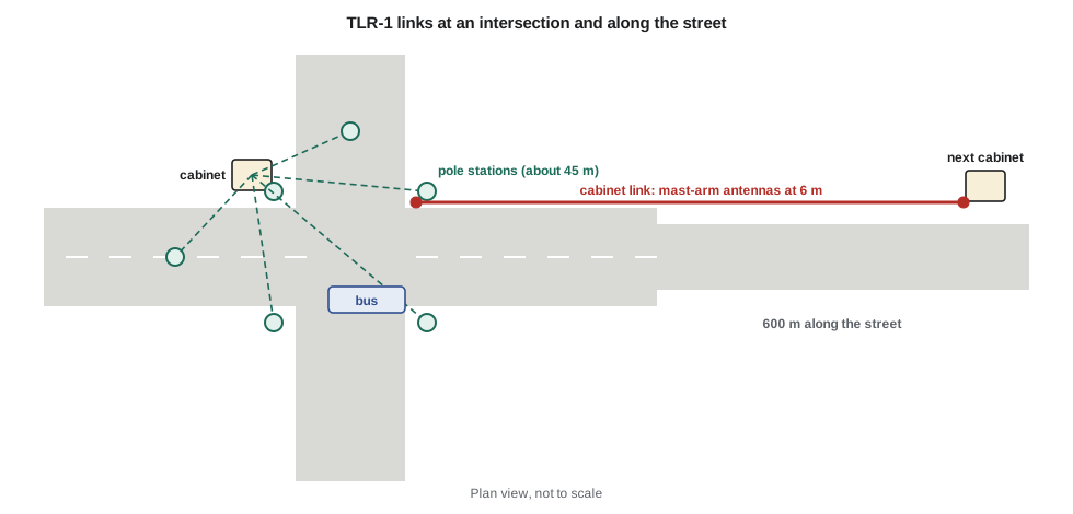
| Pole-to-cabinet range | 45 m across the intersection, with traffic | Site survey |
| Cabinet-to-cabinet range | 600 m along the street | Site survey |
| Payload | 22 bytes per packet; occasional 16 kB sound clips | Lessons 5 and 6 |
| Pole stations per cabinet | up to 8 | Intersection layouts |
| Band | 902–928 MHz, licence-exempt | Lesson 1 |
| Environment | outdoor, −40 to +74 °C in the housing | ELE-340 APS-2 design |
Spectrum rules
In Canada, a licence-exempt transmitter in the 902 to 928 MHz band must be certified against ISED's general requirements, RSS-Gen, and the specification for frequency-hopping and digital transmission systems in this band, RSS-247. Amara reads the current issue of RSS-247 alongside its U.S. counterpart, because Cedarline wants one hardware design for both markets and the two sets of limits are closely aligned. For a frequency-hopping system with a 20 dB bandwidth under 250 kHz, the rules require at least 50 hopping channels separated by at least the 20 dB bandwidth, equal average use of every channel, an average occupancy of no more than 0.4 s on any channel in a 20 s period, and allow up to 1 W of conducted output power with an antenna of up to 6 dBi. Digital transmission systems are an alternative, but they require a 6 dB bandwidth of at least 500 kHz, which a 50 kb/s signal does not have. Spurious emissions must stay at least 20 dB below the in-band level, and emissions falling in restricted bands must meet general field-strength limits.
Frequency hopping is therefore the natural fit, and it brings a benefit beyond compliance: lesson 11 showed that a retry on a channel several megahertz away sees a nearly independent fade, and an interferer on one channel blocks only a fiftieth of the hops. Amara chooses 50 channels spaced 500 kHz apart, from 902.5 to 927.0 MHz, far wider than both the signal's 20 dB bandwidth and the channel's coherence bandwidth. Each packet and its acknowledgement use one channel; the next packet hops by a pseudo-random sequence shared by all units on the intersection, so every channel is used equally over time.
Modulation, data rate and coding
The choices from lessons 6 to 10 stand. Binary GFSK with h = 0.5 and BT = 0.5 at 50 kb/s gives a constant envelope for an efficient amplifier, non-coherent detection with a short preamble, and an occupied bandwidth well under 250 kHz. Each 32-byte packet takes 5.12 ms. A 16-bit CRC ends each packet, so corrupted packets are discarded rather than acted on, and retries with acknowledgements provide reliability. Forward error correction stays off, as lesson 10 concluded, but the firmware keeps it available as a field option. Data whitening with a pseudo-random sequence keeps the transmitted spectrum smooth and gives the receiver's timing loop regular transitions, as lesson 6 advised.
Receiver and frequency plan
The transceiver is a low-IF integrated device of the kind described in lesson 4, with a datasheet sensitivity near the −105 dBm that lesson 9 computed for a 7 dB noise figure. At the pole stations, where links are short, a low-loss ceramic band-pass filter protects it from the 450 to 470 MHz land-mobile and 850 to 890 MHz cellular signals. At the cabinets, which talk 600 m along the street and sit beside technicians' trucks, Amara uses arrangement B of lesson 7: an LNA with high IIP3 and a 1 dB noise figure, then the SAW filter, then the transceiver, for a noise figure near 1.3 dB. The LNA's input is protected by a broad filter that removes signals far outside the band. Because the transceiver uses I/Q mixing with a complex IF filter, its image is an adjacent channel; with 500 kHz channel spacing, the image falls between hopping channels, never on one, and the chip's 30 dB or so of image rejection is ample.
Link budgets
The pole-to-cabinet link was examined in lesson 11: 14 dBm from the transceiver into 2 dBi antennas, 64.7 dB of free-space loss over 45 m, a 15 dB allowance for a stopped bus and 3 dB for urban noise left about 38 dB of fade margin. The cabinet link needs more care. Its 600 m path lies beyond the two-ray breakpoint of about 440 m for antennas at 6 m, so Amara uses free space to the breakpoint and 40 dB per decade beyond it. She adds 6 dB for partial obstruction of the first Fresnel zone, a shadowing allowance of 1.28σ with σ = 8 dB to cover 90 percent of locations, and 3 dB for urban noise. Directional panel antennas of 6 dBi on the mast arms point along the street.
import math
lam = 3e8 / 915e6
fspl = lambda d: 20 * math.log10(4 * math.pi * d / lam)
def loss(d, ht, hr):                       # free space to the breakpoint, then 40 dB/decade
    db = 4 * ht * hr / lam
    return fspl(d) if d <= db else fspl(db) + 40 * math.log10(d / db)
def link(name, pt, cable, gt, gr, d, ht, hr, extra, nf):
    sens = -105 + (nf - 7.0)               # lesson 9 figure, adjusted for noise figure
    pr = pt - cable + gt - loss(d, ht, hr) - extra + gr - cable
    margin = pr - (sens + 3.0)             # 3 dB urban-noise allowance
    out = 1 - math.exp(-10 ** (-margin / 10))      # Rayleigh, per attempt
    print(f"{name}: path loss {loss(d, ht, hr):5.1f} dB, received {pr:6.1f} dBm, margin {margin:5.1f} dB, "
          f"Rayleigh outage per attempt {out:.1e}, three hops {out**3:.0e}")
link('pole to cabinet   ', 14, 1, 2, 2, 45, 3.0, 2.5, 15, 7.0)
shadow = 1.28 * 8
link('cabinet A (14 dBm)', 14, 2, 6, 6, 600, 6, 6, 6 + shadow, 7.0)
link('cabinet B (14 dBm)', 14, 2, 6, 6, 600, 6, 6, 6 + shadow, 1.33)
link('cabinet C (20 dBm)', 20, 2, 6, 6, 600, 6, 6, 6 + shadow, 1.33)
# timing: packet, acknowledgement, turnaround and retries with back-off
bit = 1 / 50e3
pkt, ack, turn = 256 * bit, 128 * bit, 1.0e-3
attempt = pkt + turn + ack + turn
print(f"one attempt: {attempt*1e3:.2f} ms; three attempts with 15 ms back-off: {(3*attempt + 2*15e-3)*1e3:.1f} ms")
# channel occupancy: 8 poles, one heartbeat per second each, plus button presses and acknowledgements
tx_per_20s = 8 * 20 * 1.2
dwell = tx_per_20s / 50 * (pkt + ack)
print(f"average occupancy per channel in 20 s: {dwell*1e3:.0f} ms (limit 400 ms)")
# RF exposure from the cabinet panel antenna, option C
eirp_w = 10 ** ((20 - 2 + 6) / 10) / 1e3
for r in (0.5, 2.0):
print(f"power density at {r} m: {eirp_w / (4 * math.pi * r * r):.3f} W/m^2")pole to cabinet : path loss 64.7 dB, received -63.7 dBm, margin 38.3 dB, Rayleigh outage per attempt 1.5e-04, three hops 3e-12 cabinet A (14 dBm): path loss 89.9 dB, received -84.2 dBm, margin 17.8 dB, Rayleigh outage per attempt 1.6e-02, three hops 4e-06 cabinet B (14 dBm): path loss 89.9 dB, received -84.2 dBm, margin 23.5 dB, Rayleigh outage per attempt 4.5e-03, three hops 9e-08 cabinet C (20 dBm): path loss 89.9 dB, received -78.2 dBm, margin 29.5 dB, Rayleigh outage per attempt 1.1e-03, three hops 1e-09 one attempt: 9.68 ms; three attempts with 15 ms back-off: 59.0 ms average occupancy per channel in 20 s: 29 ms (limit 400 ms) power density at 0.5 m: 0.080 W/m^2 power density at 2.0 m: 0.005 W/m^2
The results support a simple design. The pole link has large margins. For the cabinet link, option A, without the external LNA, keeps about 18 dB: an outage near 1.6 percent per attempt against Rayleigh fading, improved to about 4 × 10⁻⁶ by three hops, which misses the requirement. Option B, with the LNA, adds about 5.7 dB and reaches about 10⁻⁷ per message on three hops at the same 14 dBm. Option C raises the cabinet transmitter to 20 dBm for another 6 dB, to about 10⁻⁹, comfortably inside the 1 W limit, and is Amara's recommendation: it costs only a small external amplifier and leaves room for an unexpected obstruction. The cabinet link is also likely to have a line-of-sight component along the street, so Rician fading would make the real outage lower than these Rayleigh figures.
Worked problem
Latency with retries
A pole station sends a 256-bit packet at 50 kb/s, waits 1 ms for the cabinet to turn around, receives a 128-bit acknowledgement and allows 1 ms more before deciding. If no acknowledgement arrives, it backs off 15 ms and retries on the next hop. Find the worst-case delivery time with three attempts.
Show solution
- \[t_{attempt} = 5.12 + 1 + 2.56 + 1 = 9.68\ \text{ms}\]
- \[t_{3} = 3(9.68) + 2(15) = 59.0\ \text{ms}\]
Answer: Three attempts fit in 59 ms, inside the 100 ms budget. The 15 ms back-off exceeds the 14 ms coherence time of lesson 11, so a retry is unlikely to meet the same fade even before hopping changes the frequency.
Access and coexistence
Up to eight pole stations share one intersection's hopping sequence, and the cabinet coordinates them. The simplest scheme gives each pole a time slot within a 100 ms frame for its heartbeat, which avoids collisions entirely, and lets button presses use any free slot with a short listen-before-talk check. The cabinet link uses a different hopping sequence offset from the intersection's so the two networks rarely land on the same channel at once. Because many other licence-exempt devices, from utility meters to wireless sensors, also use the band, the firmware records which channels fail most often. That log helps maintenance, but Amara does not drop channels automatically, because the rules require every channel in the declared set to be used equally on average.
The listen-in clips of lesson 5 use low-priority packets in slots that no button press needs. At 22 bytes of payload per packet, a 16 kB clip needs about 730 packets; spread at one per 20 ms slot, it arrives in about 15 seconds, a little longer than lesson 5's estimate because the payload per packet is smaller than assumed there. Amara records the change in the design notes and leaves the feature as specified.
Compliance and safety
Before the TLR-1 can be sold in Canada, it must be certified by ISED or a recognized certification body against RSS-Gen and RSS-247, after testing by an accredited laboratory, and it receives an ISED certification number that appears on its label. The user documentation must carry the licence-exempt statements that RSS-Gen requires, in English and French. The digital circuitry also falls under ICES-003 for unintentional emissions, as CMP-499 described. RF exposure is evaluated under RSS-102, which sets exemption levels and refers to Health Canada's Safety Code 6 for the limits. The pole stations' 14 dBm into a 2 dBi antenna is far below the exemption levels. For the cabinet link at 20 dBm into a 6 dBi panel, the code above gives a power density of about 0.08 W/m² only 0.5 m in front of the antenna and 0.005 W/m² at 2 m, while the general-public limit near 915 MHz is a few watts per square metre, so even the closest position is more than thirty times below it; the mast-arm mounting keeps people several metres away.
Designing for compliance from the start saves expensive iterations. Amara's checklist: a hopping sequence that uses all 50 channels equally and is documented for the test lab; a power setting locked in firmware at or below the certified value; harmonic filtering after the power amplifier, since the second harmonic at 1830 MHz and the third at 2745 MHz must meet the spurious limits; a crystal reference within the frequency tolerance the transceiver needs; and an antenna specified and fixed, since the certification covers a specific antenna type and gain.
Test plan
| Test | Method | Pass criterion |
|---|---|---|
| Conducted sensitivity | Signal generator through calibrated attenuators; count packet errors | PER ≤ 10⁻³ at −105 dBm (pole) and −110 dBm (cabinet) |
| Blocking | Add a 5 W-class land-mobile signal at 460 MHz through a coupler | Sensitivity loss ≤ 3 dB at the specified level |
| Intermodulation | Two tones at 1 and 2 channel offsets | Product below sensitivity at stated tone level |
| Occupied and 20 dB bandwidth | Spectrum analyzer, regulatory method | Under 250 kHz; separation rule met |
| Hopping and dwell | Spectrum analyzer in zero span over 20 s | 50 channels, ≤ 0.4 s per channel |
| Spurious and harmonics | Conducted and radiated scans to the 10th harmonic | 20 dB below in-band; restricted-band limits met |
| Latency and loss | Two-unit test with fading simulator, then field trial | All presses delivered in under 100 ms in the trial |
| Temperature | Chamber −40 to +74 °C | Frequency error and sensitivity within specification |
The field trial runs for six weeks at two Fredericton intersections, one with a busy transit route and one beside the river where the cabinet link crosses an open stretch. Leo's logging firmware records every packet's received level, channel and retry count. Over 3.1 million button and heartbeat messages, the pole links never needed a third attempt, and the cabinet link needed one on about 0.4 percent of messages, mostly when buses stopped near its path. No message was lost, and the longest delivery time was 41 ms.
Design review
Daniel's review questions are the ones an experienced engineer asks of any radio design, and each maps to a lesson. Is the bandwidth stated by the definition the rules use? Is the receiver protected from the strong signals actually present at the site? Does the sensitivity figure include implementation loss? Is the margin set against the right fading model, and are retries independent in time and frequency? Is the power the minimum needed, not the maximum allowed? Amara's answers, and the field data, satisfy him. He signs the design for a production run, with one action item: measure the cabinet link's K factor during the next trial, so that the next version can use the lower margins a Rician model would justify.
Common mistakes
MistakeChoosing the maximum allowed power because it is legal.
InsteadUse the power the link budget needs plus a sensible reserve; more power raises interference to others and exposure, and drains resources.
MistakeDesigning a hopping radio that drops bad channels without checking the rules.
InsteadThe declared channel set must be used equally on average; adaptive schemes have their own conditions.
MistakeTreating a field trial with no losses as proof of one-in-a-million reliability.
InsteadThree million messages with no losses supports, but does not prove, the target; combine trial data with the analysis.
MistakeChanging antennas after certification.
InsteadCertification covers a specific antenna type and gain; a different antenna may need new testing.
Summary and key terms
- Requirements set latency, loss rate, range and band; each design choice traces back to them.
- The 902–928 MHz rules favour frequency hopping with at least 50 channels for a narrow 50 kb/s signal, at up to 1 W with a 6 dBi antenna.
- Binary GFSK at 50 kb/s with CRC and ARQ, and hopping for frequency diversity, meets the latency and loss targets.
- The cabinet link needs a low-noise front end and modest extra power; the pole link has wide margins.
- Compliance covers bandwidth, hopping, power, spurious emissions, labelling and RF exposure.
- Bench tests, fading simulation and a field trial verify the analysis before production.
- Frequency-hopping spread spectrum
- A method in which the carrier changes among many channels in a pseudo-random sequence.
- Dwell time
- The time a hopping transmitter spends on one channel.
- Listen-before-talk
- Checking that a channel is free before transmitting.
- Certification
- Formal approval that a radio device meets the regulator's technical standards.
- RF exposure evaluation
- An assessment that radio-frequency fields near a transmitter are within public limits.
- Fading simulator
- Test equipment that imposes realistic multipath fading on a signal in the laboratory.
Practice problems
Work each problem on paper first, then reveal the answer to check.
A hopping radio uses 50 channels equally and sends 10 packets of 5 ms per second. Find the average occupancy per channel in 20 s.
Show answer
200 packets × 5 ms / 50 = 20 ms.
A cabinet transmitter at 27 dBm uses an antenna of 9 dBi. By how much must the power be reduced under the 6 dBi rule?
Show answer
By 3 dB, to 24 dBm.
Why can a 50 kb/s GFSK signal not use the digital transmission system rules in this band?
Show answer
Its 6 dB bandwidth is far below the required 500 kHz.
The cabinet link margin is 18 dB with Rayleigh fading. Estimate the per-attempt outage.
Show answer
About 10^(−1.8) ≈ 1.6 percent.
Give two reasons the TLR-1 backs off 15 ms before a retry.
Show answer
It exceeds the coherence time, so the fade has likely changed, and it reduces repeated collisions with another station.
What harmonics of 915 MHz must the output filter suppress, and why?
Show answer
1830 and 2745 MHz and higher; spurious emissions must meet the regulatory limits, including those in restricted bands.
Lesson quiz · 5 questions
Score 60% or more to complete this lesson.
Create a free account to save your progress, take quizzes and earn a certificate.