
ELE-340 · Lesson 9 of 12 · 28 min
Oscillators
Lesson 8 treated oscillation as a fault. An oscillator is the same phenomenon designed on purpose: an amplifier and a frequency-selective feedback network arranged so that the loop gain is exactly 1, with zero total phase shift, at one frequency, and less than that everywhere else. The result is a steady sine wave at that frequency, produced from a DC supply. Oscillators provide every clock in a digital system, every carrier in a radio, every test tone in a laboratory, and, in traffic control, the signal that tells a controller a vehicle is waiting. This lesson states the conditions for oscillation, analyzes the RC phase-shift, Wien-bridge and LC oscillators, explains how quartz crystals give clocks their accuracy, and introduces relaxation oscillators, which make square and triangle waves instead of sines.
Two oscillators matter to the APS-2 team. Leo wants a clean 880 Hz sine source for bench tests of the speaker amplifier, independent of the microcontroller. And Daniel has asked Amara to help a colleague with Cedarline's inductive loop detector, the card in the controller cabinet that senses vehicles through a loop of wire cut into the pavement. The loop is the inductor of an LC oscillator, and a vehicle above it changes the oscillator's frequency.
The Barkhausen criterion
Consider a loop with an amplifier A and a feedback network β but no external input, with the feedback added rather than subtracted. A signal at frequency ω_0 travelling around the loop returns multiplied by A(jω_0)β(jω_0). If that product is exactly 1, magnitude 1 and phase 0° (or a whole number of 360°), the signal sustains itself. That is the Barkhausen criterion:
The phase condition sets the frequency; the magnitude condition sets the gain needed. In practice the loop gain is made slightly greater than 1, so that noise present at switch-on grows into an oscillation, and some nonlinearity then reduces the effective gain until the amplitude settles where the loop gain is exactly 1. Too little excess gain and the oscillator may not start reliably at cold temperatures or with weak parts; too much and the waveform becomes distorted, because the limiting must clip harder. Good sine oscillators therefore use a separate, gentle amplitude control. The frequency's stability depends on how steeply the feedback network's phase changes with frequency near ω_0: a steep phase slope, which means a high quality factor Q, holds the frequency firmly even if the amplifier's phase drifts.
The RC phase-shift oscillator
The simplest RC oscillator uses an inverting amplifier, which contributes 180°, and a ladder of three RC sections that contributes the other 180° at one frequency. For three identical sections of series C and shunt R, solving the ladder gives
The circuit is easy to build, but its feedback network has a low Q, so its frequency drifts with amplifier phase, and it is awkward to tune, because all three capacitors or resistors must change together. It is used where a fixed, approximate frequency is good enough, such as in simple tone generators.
The Wien-bridge oscillator
The Wien-bridge oscillator uses a non-inverting amplifier and a feedback network of a series RC in one arm and a parallel RC in the other. At f_0 = 1/(2πRC) the network has zero phase shift and a transmission of exactly 1/3, so the amplifier needs a gain of exactly 3:
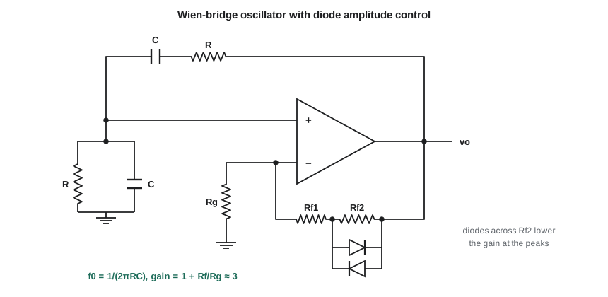
With R_f slightly more than twice R_g, the oscillation grows; it must then be tamed. William Hewlett's famous 1939 audio oscillator used a small incandescent lamp as R_g: as the amplitude grows, the filament heats, its resistance rises and the gain falls, settling smoothly at exactly 3 with very low distortion. Modern versions use back-to-back diodes in parallel with part of R_f, which reduce the gain at the waveform's peaks and give a distortion of around 1 percent, or a JFET or light-dependent resistor in an automatic gain control loop, which can reach 0.01 percent or better.
Worked problem
An 880 Hz test oscillator
Leo needs an 880 Hz sine for the speaker amplifier tests. Using C = 10 nF, choose R, then choose R_f and R_g for a small excess of gain, with diodes across part of R_f to limit the amplitude.
Show solution
- \[R = \frac{1}{2\pi \times 880 \times 10\ \text{nF}} \approx 18.1\ \text{k}\Omega \to 18\ \text{k}\Omega \qquad f_0 = \frac{1}{2\pi \times 18\ \text{k} \times 10\ \text{nF}} \approx 884\ \text{Hz}\]
- Choose R_g = 10 kΩ and R_f = 22 kΩ made of 15 kΩ plus 7.5 kΩ, with the diodes across the 7.5 kΩ:
- \[A_{small} = 1 + \frac{22.5}{10} = 3.25 \qquad A_{peaks} \to 1 + \frac{15}{10} = 2.5\]
Answer: The oscillator runs at about 884 Hz, close enough to 880 Hz for amplifier testing, and a 1 percent capacitor would move it by about 9 Hz. At small amplitude the gain of 3.25 makes the oscillation grow; as the peaks exceed a diode drop across the 7.5 kΩ resistor, the gain at the peaks falls toward 2.5, and the amplitude settles where the average gain over a cycle is 3, a little more than two diode drops in amplitude at the op amp output.
LC oscillators
Above a few hundred kilohertz, and wherever a sharper resonance is wanted, oscillators use inductors and capacitors. The Colpitts oscillator takes its feedback from a capacitive divider, C_1 and C_2, across an inductor; the Hartley from a tapped inductor; the Clapp adds a small series capacitor to the Colpitts inductor so that transistor capacitances matter less. For the Colpitts, the frequency is set by the inductor and the series combination of the two capacitors, and the transistor must supply enough gain to overcome the divider's attenuation:
Here R is the total resistance loading the tank, including the inductor's own loss resistance reflected as a parallel resistance. An LC tank's Q, from tens to a few hundred, is far higher than an RC network's, so LC oscillators hold their frequency better, and the tank filters harmonics, giving a cleaner sine.
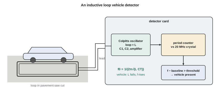
The inductive loop detector is an LC oscillator whose inductor is a few turns of wire in a saw cut in the road. The loop and its lead-in typically total on the order of 100 µH, and detectors run in the tens of kilohertz. A vehicle's metal body, sitting in the loop's magnetic field, carries eddy currents that oppose the field and reduce the inductance slightly, so the frequency rises. The detector measures the frequency continuously, tracks the slow drift caused by temperature and moisture, and reports a vehicle when the frequency rises above the tracked baseline by more than a sensitivity threshold that the technician sets for the lane.
Worked problem
Frequency shift from a vehicle
A loop and lead-in total 100 µH, with C_1 = C_2 = 0.1 µF. Find the oscillation frequency, and the frequency change when a car reduces the inductance by 1 percent.
Show solution
- \[C_T = \frac{0.1 \times 0.1}{0.2} = 0.05\ \mu\text{F} \qquad f_0 = \frac{1}{2\pi\sqrt{100\ \mu\text{H} \times 0.05\ \mu\text{F}}} \approx 71.2\ \text{kHz}\]
- Since f ∝ L^(−1/2), a small fractional change in L gives half that change in f, in the opposite direction:
- \[\frac{\Delta f}{f} \approx -\frac{1}{2}\frac{\Delta L}{L} = +0.5\ \% \qquad \Delta f \approx 356\ \text{Hz}\]
Answer: The oscillator runs near 71 kHz, and a 1 percent inductance drop raises the frequency by about 356 Hz. Smaller vehicles, especially bicycles and motorcycles, produce much smaller changes, so the detector must resolve frequency changes of a few hertz against a slowly drifting baseline, which is a measurement problem the code below explores.
import cmath, math
# 1. Three-section RC phase-shift ladder (series C, shunt R): find f where the phase is 180 deg
def ladder_A(f, R, C):
    """Return Vin/Vout of three series-C / shunt-R sections with an open output (ABCD chain)."""
    s = 2j * math.pi * f
    a, b, c, d = 1, 0, 0, 1                # ABCD matrix of the chain so far
    Z, Y = 1 / (s * C), 1 / R
    for _ in range(3):
        a, b, c, d = a, a * Z + b, c, c * Z + d          # series impedance Z
        a, b, c, d = a + b * Y, b, c + d * Y, d          # shunt admittance Y
    return a
R, C = 10e3, 10e-9
lo, hi = 100.0, 10e3
s_lo = ladder_A(lo, R, C).imag > 0
for _ in range(100):                     # imaginary part of A changes sign at f0
    m = math.sqrt(lo * hi)
    if (ladder_A(m, R, C).imag > 0) == s_lo: lo = m
    else: hi = m
A = ladder_A(m, R, C)
print(f"phase-shift: f0 = {m:.1f} Hz (formula {1/(2*math.pi*math.sqrt(6)*R*C):.1f} Hz), Vin/Vout = {A.real:.2f}")
# 2. Wien network at f0
R, C = 18e3, 10e-9
f0 = 1 / (2 * math.pi * R * C)
w = 2 * math.pi * f0
b = 1 / (3 + 1j * (w * R * C - 1 / (w * R * C)))
print(f"Wien: f0 = {f0:.0f} Hz, |beta| = {abs(b):.4f}, phase = {math.degrees(cmath.phase(b)):.2f} deg")
# 3. Loop detector: frequency, vehicle shift, and how long to count for a 2 Hz resolution
L, C1, C2 = 100e-6, 0.1e-6, 0.1e-6
CT = C1 * C2 / (C1 + C2)
f = 1 / (2 * math.pi * math.sqrt(L * CT))
for dl in (0.01, 0.001, 0.0002):
    fv = 1 / (2 * math.pi * math.sqrt(L * (1 - dl) * CT))
    print(f"loop: dL/L = -{dl*100:.2f} %: f rises from {f:.0f} Hz by {fv - f:.1f} Hz")
print(f"counting cycles: a 2 Hz resolution needs a {1/2:.1f} s gate")
fref, N = 20e6, 1000                     # time N loop cycles with a 20 MHz reference clock
counts = N / f * fref
print(f"period method: {N} cycles = {counts:.0f} reference counts in {N/f*1e3:.1f} ms; 1 count = {f/counts:.2f} Hz")phase-shift: f0 = 649.7 Hz (formula 649.7 Hz), Vin/Vout = -29.00 Wien: f0 = 884 Hz, |beta| = 0.3333, phase = 0.00 deg loop: dL/L = -1.00 %: f rises from 71176 Hz by 358.6 Hz loop: dL/L = -0.10 %: f rises from 71176 Hz by 35.6 Hz loop: dL/L = -0.02 %: f rises from 71176 Hz by 7.1 Hz counting cycles: a 2 Hz resolution needs a 0.5 s gate period method: 1000 cycles = 280993 reference counts in 14.0 ms; 1 count = 0.25 Hz
The ladder solution confirms the textbook result: the phase reaches 180° at 1/(2π√6RC) and the network attenuates by 29 there. The loop detector lines show the measurement challenge. A car's 1 percent change gives over 350 Hz, easy to see, but a 0.02 percent change, the kind of signal a bicycle gives on some loops, is only about 7 Hz. Counting the loop's own cycles for a 2 Hz resolution would take half a second, too slow for a traffic controller. Instead, detectors time a fixed number of loop cycles against a fast crystal reference: 1,000 cycles take about 14 ms, and with a 20 MHz reference each count corresponds to well under 1 Hz.
Crystal oscillators
A quartz crystal is a thin slice of quartz with electrodes on both faces. Quartz is piezoelectric: a voltage bends it and bending produces a voltage, so a crystal cut to a mechanical resonance behaves electrically like a series RLC circuit with an extraordinarily small capacitance C_m, a large inductance L_m and a small loss resistance R_m, all in parallel with the electrode capacitance C_0 of a few picofarads. It has a series resonance where L_m and C_m resonate, and a parallel resonance slightly higher where L_m resonates with C_m in series with C_0. Between the two the crystal is inductive, and a crystal oscillator operates there, using the crystal as the inductor of a Colpitts-type circuit.
The crystal's Q is typically 10⁴ to 10⁶, a hundred to ten thousand times that of an LC tank, so its frequency hardly depends on the circuit. A general-purpose crystal is specified to about ±10 to ±50 parts per million at room temperature, with a similar further drift over temperature. Every microcontroller clock oscillator is a Pierce oscillator: an inverting amplifier on the chip, the crystal from its output back to its input, and a capacitor from each crystal pin to ground. The crystal is specified for a particular load capacitance C_L, and the two capacitors must provide it together with stray capacitance:
Worked problem
Load capacitors for the microcontroller crystal
The APS-2 microcontroller uses an 8 MHz crystal specified for C_L = 12 pF. The board traces and the chip pins add about 3 pF of stray capacitance. Choose C_1 and C_2.
Show solution
- \[C_1 = C_2 = 2(12 - 3) = 18\ \text{pF}\]
Answer: Two 18 pF capacitors put the crystal at its specified load, so it runs within its rated tolerance. Using much smaller capacitors would pull the frequency high by tens of parts per million, enough to disturb a serial link's timing if it were already near its error budget. Amara also checks the oscillator's start-up margin: the amplifier's negative resistance should exceed the crystal's maximum equivalent series resistance by a factor of about five, so it starts reliably at −40 °C.
Relaxation oscillators
Not every oscillator needs to make a sine. A relaxation oscillator charges a capacitor until a threshold is reached, then switches and discharges it, repeating indefinitely; its output is a square wave, with a triangle or exponential ramp on the capacitor. The op amp astable multivibrator uses a comparator with positive feedback (a Schmitt trigger) and an RC network; with the comparator's thresholds at ±βV_sat, its period is
which for β = 0.5 gives T ≈ 2.2RC. The classic 555 timer works the same way with internal comparators at one-third and two-thirds of the supply. Ring oscillators, an odd number of inverters in a loop, are the simplest relaxation-type oscillators of all and sit inside chips as test structures and clock sources. The class-D amplifier of lesson 11 needs a triangle wave of several hundred kilohertz, which is made by a relaxation oscillator whose capacitor is charged by a constant current, giving straight ramps instead of exponentials.
Unwanted oscillation and frequency stability
Everything that makes an oscillator work can make an amplifier misbehave: a transistor with long leads and stray capacitance can form a Colpitts oscillator at hundreds of megahertz without anyone intending it. Such parasitic oscillations are cured with small series resistors in base or gate leads, ferrite beads and short layout. For deliberate oscillators, the quality of the output is described by frequency stability over time and temperature, and by phase noise, the small random wandering of phase that appears as jitter in digital clocks and as noise skirts around a radio carrier. Both improve with higher resonator Q, which is why crystals, and for the best references, temperature-controlled or atomic standards, are used where timing matters.
Common mistakes
MistakeDesigning an oscillator with a loop gain of exactly 1.
InsteadGive it some excess gain to start reliably, and a gentle limiting mechanism to settle the amplitude.
MistakeLimiting a Wien oscillator by letting the op amp clip.
InsteadClipping causes heavy distortion; use diodes, a thermistor or an AGC loop.
MistakeOmitting the stray capacitance when choosing crystal load capacitors.
InsteadC_L includes a few picofarads of stray capacitance; C₁ = C₂ = 2(C_L − C_stray).
MistakeMeasuring a small frequency shift by counting cycles over a short gate.
InsteadTime many cycles against a fast reference instead.
Summary and key terms
- An oscillator satisfies Barkhausen's criterion: loop gain 1 with zero phase at one frequency.
- Excess gain starts the oscillation; nonlinearity or AGC then holds the loop gain at exactly 1.
- RC phase-shift: f₀ = 1/(2π√6RC), gain ≥ 29; Wien bridge: f₀ = 1/(2πRC), gain 3.
- LC oscillators (Colpitts, Hartley, Clapp) give higher Q and cleaner sines; f₀ = 1/(2π√(LC_T)).
- Loop detectors use the road loop as an LC oscillator's inductor; a vehicle lowers L and raises f by about half of |ΔL/L|.
- Crystals have Q of 10⁴ to 10⁶; Pierce oscillators need the specified load capacitance.
- Relaxation oscillators produce square and triangle waves by charging a capacitor between thresholds.
- Barkhausen criterion
- The condition Aβ = 1, with magnitude 1 and zero phase, for a sustained oscillation.
- Wien-bridge oscillator
- A sine oscillator using a series and a parallel RC network with a non-inverting gain of 3.
- Colpitts oscillator
- An LC oscillator whose feedback comes from a capacitive divider across the inductor.
- Inductive loop detector
- A vehicle detector whose road loop is the inductor of an oscillator.
- Quartz crystal
- A piezoelectric resonator with a very high Q, used to set oscillator frequencies precisely.
- Load capacitance
- The capacitance a crystal must see in its circuit to oscillate at its specified frequency.
- Relaxation oscillator
- An oscillator that charges and discharges a capacitor between two thresholds, producing a non-sinusoidal wave.
Practice problems
Work each problem on paper first, then reveal the answer to check.
Find f₀ for a Wien bridge with R = 10 kΩ and C = 4.7 nF.
Show answer
1/(2π × 10 k × 4.7 nF) ≈ 3.39 kHz.
A phase-shift oscillator uses R = 4.7 kΩ and C = 10 nF. Find f₀.
Show answer
1/(2π√6 × 4.7 k × 10 nF) ≈ 1.38 kHz.
A Colpitts oscillator has L = 47 µH, C₁ = 1 nF and C₂ = 4.7 nF. Find f₀.
Show answer
C_T ≈ 0.825 nF; f₀ = 1/(2π√(47 µ × 0.825 n)) ≈ 808 kHz.
A loop detector runs at 50 kHz. A vehicle lowers L by 2 percent. Estimate the frequency change.
Show answer
About +1 percent, +500 Hz.
A crystal needs C_L = 18 pF with 4 pF stray. Choose equal load capacitors.
Show answer
2 × (18 − 4) = 28 pF; use 27 pF.
An op amp astable has β = 0.5, R = 10 kΩ and C = 100 nF. Find its frequency.
Show answer
T = 2 × 10 k × 100 n × ln 3 ≈ 2.2 ms, about 455 Hz.
Lesson quiz · 5 questions
Score 60% or more to complete this lesson.
Create a free account to save your progress, take quizzes and earn a certificate.