
ELE-340 · Lesson 11 of 12 · 25 min
Class D and switching amplifiers
A linear output stage wastes power because its transistors sit partway on, with voltage across them and current through them at the same time. A switching amplifier avoids that by using its transistors only as switches: fully on, with almost no voltage across them, or fully off, with almost no current through them. The output is a fast square wave whose average follows the audio signal, and a low-pass filter recovers the audio. Such class D amplifiers reach efficiencies of 85 to 95 percent at full power, which is why they drive the speakers in phones, laptops, car audio and almost every powered loudspeaker made today. This lesson explains pulse-width modulation, half-bridge and full-bridge outputs, the output filter, the losses that remain, the distortion and interference that switching brings, and how class D compares with class AB for the APS-2.
Daniel has asked Amara to evaluate a class D option before committing to the class AB design. A class D stage would dissipate a fraction of the class AB stage's heat, which matters in a sealed housing at 74 °C. Against that, it switches amperes in nanoseconds a few centimetres from a microphone input, a cellular modem and, in the cabinet below, the loop detector oscillators of lesson 9.
Pulse-width modulation
The most common class D modulator compares the audio signal with a triangle wave at a much higher frequency, the carrier or switching frequency f_s, typically 250 kHz to 1 MHz. Whenever the audio is above the triangle, the comparator's output is high; whenever it is below, low. The result is a train of pulses at f_s whose width, or duty cycle D, follows the audio. A half-bridge output stage, two switches between the rails, reproduces the comparator output at power level, so the switch node alternates between +V_DD and −V_DD, and its average over each switching period is
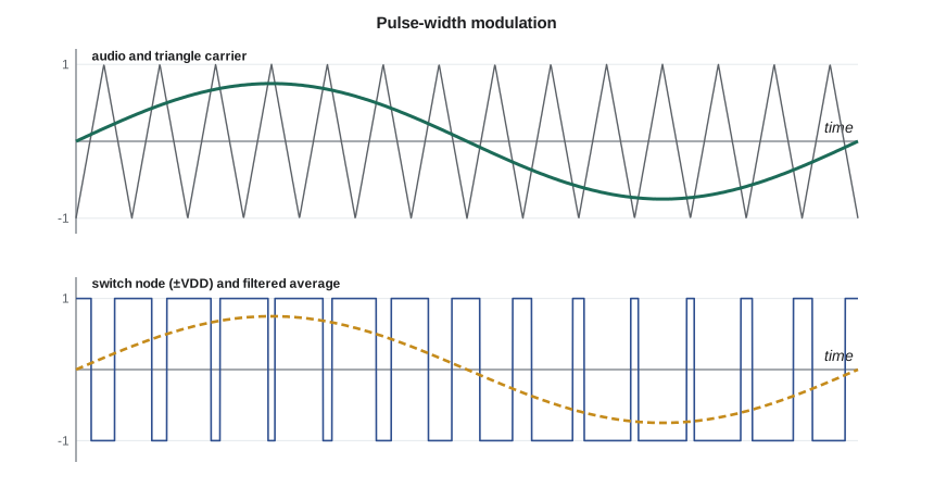
The modulation index m is the ratio of the audio peak to the triangle peak; at m = 1 the pulses just reach 0 and 100 percent duty. The spectrum of the PWM wave contains the audio, unchanged, plus components clustered around f_s, 2f_s and higher harmonics, with sidebands spaced by the audio frequency. As long as f_s is well above the audio band, a low-pass filter can remove everything but the audio. A rule of thumb is f_s at least ten times the highest audio frequency, and higher if the feedback loop is to have useful gain across the audio band.
Half-bridge and full-bridge outputs
A half-bridge drives the speaker from one switch node to ground and needs a split supply, ±V_DD. A full bridge, also called a bridge-tied load (BTL), uses two half-bridges driven in opposite phase, with the speaker between their outputs. Each end swings between 0 and V_DD on a single supply, but the voltage across the speaker swings between +V_DD and −V_DD, so a full bridge on a single supply gives the same speaker voltage as a half-bridge on a split supply of twice the total voltage. The full bridge also avoids two problems of the half-bridge: there is no DC across the speaker at idle, and there is no supply pumping, the effect in which a half-bridge returns energy from the filter inductor to one rail, pushing its voltage up at low audio frequencies.
Worked problem
Power from a 12 V full bridge
A class D option for the APS-2 would run a full bridge from the station's 12 V rail into the 8 Ω speaker. Allowing a maximum modulation index of 0.9 and neglecting switch drops, find the maximum continuous sine power, and the modulation index needed for the rated 4 W.
Show solution
- \[V_p = 0.9 \times 12 = 10.8\ \text{V} \qquad P_{max} = \frac{10.8^2}{2 \times 8} \approx 7.3\ \text{W}\]
- \[V_p(4\ \text{W}) = \sqrt{2 \times 8 \times 4} = 8.0\ \text{V} \qquad m = \frac{8.0}{12} \approx 0.67\]
Answer: A full bridge on the single 12 V rail can deliver about 7 W, comfortably above the 4 W rating, so the ±12 V rails that the class AB design needs would not be required for the class D option. Rated output needs a modulation index of about two thirds.
The output filter
The switch node carries the full rail voltage as a square wave, and the speaker should see only audio. Most class D amplifiers use a second-order LC low-pass filter between each switch node and the speaker. Designed as a Butterworth filter, maximally flat, for a load resistance R and a corner frequency f_c,
The filter attenuates at 40 dB per decade above f_c. With f_c near 40 kHz and f_s at 400 kHz, the carrier is reduced by about 40 dB. There is a catch: a loudspeaker is not a resistor. Its impedance rises with frequency because of the voice coil's inductance, so the filter, designed for 8 Ω, sees a higher impedance near f_c and peaks. A Zobel network, a series resistor and capacitor across the speaker terminals, keeps the load near 8 Ω at high frequencies. A real speaker cable is also an antenna, which is why the filter sits close to the switches and why the speaker wires in the APS-2 would be twisted and kept short.
Worked problem
Filter for the APS-2 class D option
Design a Butterworth LC filter with f_c = 40 kHz for an 8 Ω load, and estimate the carrier attenuation at f_s = 400 kHz.
Show solution
- \[L = \frac{1.414 \times 8}{2\pi \times 40\,000} \approx 45\ \mu\text{H} \qquad C = \frac{1}{1.414 \times 8 \times 2\pi \times 40\,000} \approx 352\ \text{nF} \to 330\ \text{nF}\]
- \[|H(400\ \text{kHz})| \approx \Big(\frac{40}{400}\Big)^2 = 0.01 \;(-40\ \text{dB})\]
Answer: A 47 µH inductor rated for the peak current without saturating and a 330 nF film capacitor give a corner near 40 kHz and about 40 dB of carrier attenuation. In a full bridge, one such filter is placed on each output, with the capacitors referenced to ground or connected across the speaker, depending on the common-mode filtering required. The simulation below checks the result.
import math
# Simulate a half-bridge class D stage: natural-sampling PWM, then an LC filter into 8 ohms.
VDD, fs, fa, m = 12.0, 400e3, 1e3, 0.67
L, C, R = 45e-6, 352e-9, 8.0
steps_per_carrier = 200
dt = 1 / (fs * steps_per_carrier)
N = int(round(2e-3 / dt))                # simulate 2 ms; analyze the second millisecond
iL = vC = 0.0
out = []
for n in range(N):
    t = n * dt
    ph = (t * fs) % 1.0
    tri = 4 * ph - 1 if ph < 0.5 else 3 - 4 * ph      # triangle from -1 to +1
    vsw = VDD if m * math.sin(2 * math.pi * fa * t) > tri else -VDD
    iL += (vsw - vC) / L * dt                          # semi-implicit Euler
    vC += (iL - vC / R) / C * dt
    if n >= N // 2:
        out.append(vC)
M = len(out)
re = sum(out[k] * math.cos(2 * math.pi * k / M) for k in range(M)) * 2 / M
im = sum(out[k] * math.sin(2 * math.pi * k / M) for k in range(M)) * 2 / M
amp = math.hypot(re, im)
ripple = max(abs(out[k] - (re * math.cos(2*math.pi*k/M) + im * math.sin(2*math.pi*k/M))) for k in range(M))
print(f"audio amplitude at the speaker: {amp:.2f} V peak (ideal m*VDD = {m*VDD:.2f} V), power {amp**2/(2*R):.2f} W")
print(f"largest residual (carrier ripple and error): {ripple*1e3:.0f} mV")
# Loss budget for a 12 V full bridge at 4 W
Rds, tsw, Qg, Vg, DCR, Pq = 0.10, 10e-9, 5e-9, 5.0, 0.05, 0.10
Irms = math.sqrt(4.0 / R); Iavg = 2 * math.sqrt(2) * Irms / math.pi
Pcond = Irms ** 2 * (2 * Rds + 2 * DCR)
Psw = 2 * 12 * Iavg * (2 * tsw) * fs / 2
Pgate = 4 * Qg * Vg * fs
Ptot = Pcond + Psw + Pgate + Pq
print(f"losses at 4 W: conduction {Pcond:.3f}, switching {Psw:.3f}, gate {Pgate:.3f}, quiescent {Pq:.2f} -> efficiency {100*4/(4+Ptot):.0f} %")audio amplitude at the speaker: 8.04 V peak (ideal m*VDD = 8.04 V), power 4.04 W largest residual (carrier ripple and error): 184 mV losses at 4 W: conduction 0.150, switching 0.061, gate 0.040, quiescent 0.10 -> efficiency 92 %
The simulated speaker voltage has an audio amplitude close to m × V_DD, so the PWM and filter reproduce the signal as the average formula predicts. A residual of about 0.2 V remains at the carrier frequency; that ripple is inaudible and carries little power into the speaker, but it radiates from the speaker cable, which is why the filter and cable layout matter for interference. The loss budget gives an efficiency near 90 percent at 4 W, against about 52 percent for the class AB stage at the same output, so the class D option would dissipate about 0.35 W instead of about 3.6 W.
Losses that remain
Class D losses fall into four groups. Conduction loss is I²R in the switches' on-resistance and the inductors' winding resistance, and it scales with output power. Switching loss occurs during each transition, when voltage and current overlap for a few nanoseconds; it scales with the supply voltage, the current and the switching frequency. Gate-drive loss charges and discharges the MOSFET gates every cycle, Q_gV_gf_s per switch. And fixed losses, the modulator, the bias circuits and the ripple current that circulates in the filter inductor even at idle, are present all the time. At full power, conduction usually dominates and efficiency is high; at very low power, fixed losses dominate and efficiency falls, though the absolute dissipation is small. Higher switching frequencies allow smaller filters and better feedback but cost switching and gate losses, which is one reason most designs sit between 300 kHz and 1 MHz.
Distortion, dead time and feedback
Class D distortion comes from different sources than in linear stages. The two switches in each half-bridge must never be on together, or they short the supply through themselves, a fault called shoot-through. The driver therefore inserts a dead time of tens of nanoseconds between turning one switch off and the other on. During the dead time the inductor current flows through a body diode, and the switch node's voltage depends on the current's direction, which distorts the pulse widths near zero crossings, a switching cousin of crossover distortion. Supply ripple is another: since the output pulses swing between the rails, an open-loop class D stage has essentially no power-supply rejection, and any ripple appears in the audio. Good class D amplifiers therefore include feedback, either from the switch node with an integrator around the modulator, or from after the filter, which also corrects the filter's dependence on the speaker load. With feedback, distortion below 0.1 percent and supply rejection of 60 dB or more are routine.
Interference and compliance
A class D stage switching a 12 V rail with 10 ns edges at 400 kHz produces energy at harmonics extending well into the tens of megahertz. Without care it can disturb nearby radio receivers and sensitive analog circuits, and it can cause a product to fail the radiated-emission limits that apply to digital and switching equipment. In Canada those requirements are set for equipment of this kind by Innovation, Science and Economic Development Canada, and in the United States by the Federal Communications Commission rules for unintentional radiators. Mitigations include short, twisted speaker leads, ferrite beads, slower edge rates, a modulator with a spread-spectrum or randomized carrier so that energy does not pile up at single frequencies, careful ground planes, and keeping the switching loop between the bridge and its decoupling capacitors as small as possible.
| Criterion | Class AB (discrete) | Class D (full bridge, 12 V) |
|---|---|---|
| Efficiency at 4 W | About 52 % | About 90 % |
| Worst-case dissipation | About 3.6 W, needs a 12 °C/W heat sink | About 0.5 W, board copper is enough |
| Supplies | ±12 V split rails | Single 12 V rail |
| Distortion at rated output | Very low with feedback | Low with feedback; depends on dead time and supply |
| Interference risk | Minimal | Switching harmonics near the microphone input, modem and loop detectors |
| Parts | Discrete, widely second-sourced | Usually a dedicated integrated circuit |
| Idle dissipation | About 0.7 W (quiescent current) | About 0.1–0.3 W |
The comparison does not have a single winner. Class D is clearly better for heat and needs one supply rail. Class AB is simpler to make quiet near sensitive circuits, has no filter whose response depends on the speaker, and can be built from discrete parts that road authorities' twenty-year support requirement makes attractive. Daniel and Amara decide to carry the class AB design through the capstone in lesson 12, with the class D option kept as a documented alternative should a future housing need less heat.
Beyond class D
Other classes trade efficiency against linearity in between. Class G uses two or more supply rails and switches the output stage to the higher rail only during loud peaks, reducing average dissipation for speech and music, which spend most of their time far below peak. Class H modulates the supply rail itself to track the signal. Sigma-delta modulators replace the triangle comparator with a noise-shaping loop that pushes quantization noise above the audio band, and fully digital amplifiers generate the PWM directly from digital audio data. The same switching principles drive the motor inverters and DC-DC converters of ELE-470, where efficiency matters at kilowatts rather than watts.
Common mistakes
MistakeDesigning the LC filter for 8 Ω and assuming the speaker is a resistor.
InsteadAdd a Zobel network or check the response with the real speaker impedance.
MistakeRunning a half-bridge class D stage with no attention to supply pumping.
InsteadUse a full bridge or enough bulk capacitance on each rail.
MistakeTurning both half-bridge switches on together during transitions.
InsteadInsert dead time to prevent shoot-through, and accept or correct its distortion.
MistakeAssuming switching amplifiers reject supply ripple.
InsteadOpen-loop class D has almost no PSRR; use feedback and a clean supply.
Summary and key terms
- Class D uses transistors as switches; PWM encodes the audio in pulse widths at a switching frequency far above audio.
- Average switch-node voltage = mV_DD sin ωt; m is the modulation index.
- A full bridge doubles the speaker swing on a single supply and avoids DC offset and supply pumping.
- An LC filter, L = √2R/(2πf_c), C = 1/(√2R·2πf_c), removes the carrier at 40 dB per decade.
- Losses: conduction, switching, gate drive and fixed losses; efficiency is typically 85–95 % at full power.
- Dead time prevents shoot-through but adds distortion; feedback reduces distortion and supply sensitivity.
- Switching edges create interference; layout, filtering and spread-spectrum modulation keep products compliant.
- Class D amplifier
- An amplifier whose output transistors operate as switches, with the signal encoded in pulse widths.
- Pulse-width modulation
- Encoding a signal in the duty cycle of a constant-frequency pulse train.
- Modulation index
- The ratio of the signal peak to the carrier peak in a PWM modulator.
- Bridge-tied load
- A load connected between the outputs of two amplifiers driven in opposite phase.
- Dead time
- A short interval during which both switches of a half-bridge are off, preventing shoot-through.
- Shoot-through
- Simultaneous conduction of both switches in a half-bridge, shorting the supply.
- Zobel network
- A series RC across a loudspeaker that keeps its impedance near resistive at high frequencies.
Practice problems
Work each problem on paper first, then reveal the answer to check.
A half-bridge on ±20 V runs at m = 0.5. Find the peak of the averaged output.
Show answer
0.5 × 20 = 10 V.
Find the maximum sine power from a 24 V full bridge into 4 Ω at m = 0.9.
Show answer
V_p = 21.6 V; P = 21.6²/8 ≈ 58 W.
Design a Butterworth filter for 4 Ω with f_c = 30 kHz.
Show answer
L = 1.414 × 4/(2π × 30 k) ≈ 30 µH; C = 1/(1.414 × 4 × 2π × 30 k) ≈ 938 nF.
How much does a second-order filter with f_c = 50 kHz attenuate a 500 kHz carrier?
Show answer
About (50/500)² = 0.01, or 40 dB.
A MOSFET has Q_g = 8 nC driven at 10 V and 500 kHz. Find its gate-drive loss.
Show answer
8 n × 10 × 500 k = 40 mW.
Why does a class D amplifier's efficiency fall at very low output power?
Show answer
Fixed losses (gate drive, bias, ripple current) stay the same while output power shrinks.
Lesson quiz · 5 questions
Score 60% or more to complete this lesson.
Create a free account to save your progress, take quizzes and earn a certificate.