
ELE-250 · Lesson 8 of 12 · 22 min
Frequency response and filtering
Lesson 7 showed that an LTI system multiplies the spectrum of its input by its frequency response, H(jω). This lesson puts that fact to work. Amara's microphone channel needs three filters. A high-pass filter must remove the 60 Hz hum picked up from the cabinet wiring, a low-pass filter in front of the ADC must remove everything that the 8 kHz sampling rate cannot represent, and the noise detector needs a band-pass filter that keeps the frequencies where traffic is loud and people are sensitive. Designing them means reading and drawing frequency responses, expressing gains in decibels, and accepting that real filters only approximate the ideal shapes.
What the frequency response means
Because complex exponentials are eigenfunctions of LTI systems, a sinusoid x(t) = A cos(ωt + φ) passes through a stable LTI system and comes out as a sinusoid of the same frequency:
The magnitude |H(jω)| is the gain at that frequency and the angle ∠H(jω) is the phase shift. Measuring a filter on the bench means exactly this: drive it with a sine at one frequency, measure the ratio of output to input amplitude and the time shift between them, then step to the next frequency. For a system described by its impulse response, H(jω) is the Fourier transform of h(t); for a circuit, it comes from replacing each capacitor by 1/(jωC) and each inductor by jωL and solving the circuit as a voltage divider.
Decibels
Gains are usually quoted in decibels (dB), 20 log₁₀|H|, because filters span huge ranges and because the gains of cascaded stages, which multiply, add in decibels. A gain of 1 is 0 dB, 10 is +20 dB, 0.1 is −20 dB and 0.01 is −40 dB. The factor 1/√2 ≈ 0.707 is −3 dB, the point where the output power has fallen by half. A useful memory aid: every factor of 2 in amplitude is about 6 dB, and every factor of 10 is 20 dB. Frequencies are plotted on a logarithmic axis, measured in decades (factors of 10) or octaves (factors of 2).
The first-order low-pass filter and its Bode plot
The RC low-pass filter has frequency response
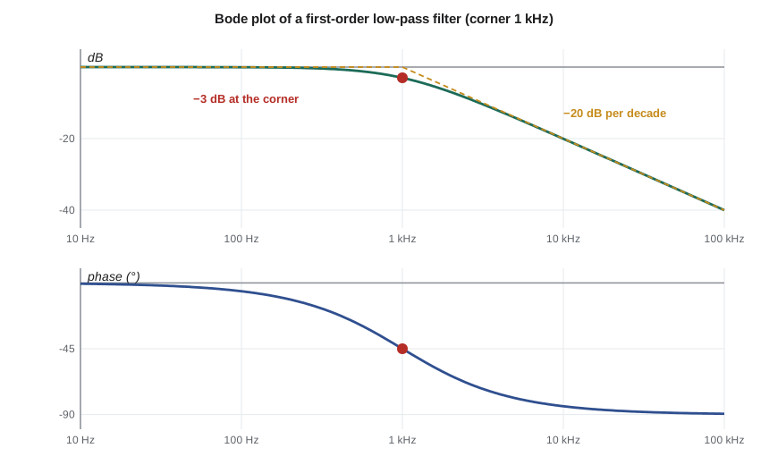
Its magnitude in decibels is −10 log₁₀(1 + (ω/ω_c)²) and its phase is −arctan(ω/ω_c). A Bode plot draws both against log frequency. Well below the corner frequency ω_c, the magnitude is close to 0 dB and the phase close to 0°. Well above it, the magnitude falls by 20 dB per decade, or 6 dB per octave, and the phase approaches −90°. At the corner itself, the magnitude is exactly −3 dB and the phase −45°. Drawing the two straight-line asymptotes, flat to the corner and then sloping at −20 dB per decade, gives a sketch that is never more than 3 dB wrong. For Amara's filter, RC = 0.16 ms, so ω_c = 6,250 rad/s and f_c = ω_c/2π ≈ 995 Hz.
Worked problem
Gain of the first-order filter at three frequencies
Find the gain in decibels and the phase of the RC filter (f_c ≈ 995 Hz) at 100 Hz, 995 Hz and 10 kHz.
Show solution
- The ratio f/f_c is 0.1, 1 and about 10.05. Use |H| = 1/√(1 + (f/f_c)²).
- \[f = 100\ \text{Hz}: \ |H| = \frac{1}{\sqrt{1.01}} = 0.995 \;\to\; -0.04\ \text{dB}, \quad \angle H = -5.7^\circ\]
- \[f = 995\ \text{Hz}: \ |H| = \frac{1}{\sqrt{2}} = 0.707 \;\to\; -3.0\ \text{dB}, \quad \angle H = -45^\circ\]
- \[f = 10\ \text{kHz}: \ |H| = \frac{1}{\sqrt{1 + 101}} = 0.099 \;\to\; -20.1\ \text{dB}, \quad \angle H = -84.3^\circ\]
Answer: The filter passes 100 Hz essentially unchanged, halves the power at its corner and cuts 10 kHz by about 20 dB, one decade past the corner, as the asymptote predicts.
High-pass, band-pass and notch filters
Swapping the resistor and capacitor turns the low-pass circuit into a high-pass filter, with H(jω) = (jω/ω_c)/(1 + jω/ω_c). Its magnitude rises at +20 dB per decade below the corner and is flat above it. Amara puts one in front of the microphone preamplifier with a corner at 200 Hz to suppress the 60 Hz hum. At 60 Hz, f/f_c = 0.3 and the gain is 0.3/√1.09 ≈ 0.287, or −10.8 dB. That is a useful reduction but not a cure, so she also re-routes the microphone cable away from the cabinet's power wiring. A first-order filter is gentle; to remove an interfering frequency much more strongly, engineers use steeper filters or a notch filter tuned to that one frequency.
A band-pass filter passes a range between two corners and attenuates both sides; cascading a high-pass and a low-pass filter makes a simple one. The noise detector uses a band-pass filter from about 300 Hz to 3 kHz, roughly the range where traffic noise and human hearing overlap most, while the anti-aliasing filter and the hum filter handle the edges. A notch, or band-stop, filter removes a narrow band and passes everything else.
Ideal filters and why they cannot be built
The ideal low-pass filter has gain 1 up to a cut-off frequency ω_c and gain 0 above it, with zero phase. It would remove all high-frequency noise and leave the wanted band untouched. Its impulse response, found from the inverse Fourier transform of a rectangle in frequency, is a sinc function in time, h(t) = (ω_c/π)·sin(ω_c t)/(ω_c t). That sinc extends forever in both directions, including negative time, so the ideal filter is non-causal: it would have to respond before its input arrived. Every real filter is therefore a compromise. Its specification lists a passband in which the gain may ripple by a small amount, a stopband in which the gain must stay below some level, and a transition band between them. Sharper transitions cost more filter stages, more components and more delay.
Higher-order filters
Cascading identical first-order stages with buffers between them multiplies their responses, which adds their decibel gains: two stages fall at −40 dB per decade, and n stages at −20n dB per decade. The corner becomes soft, though, because each stage is already 3 dB down at the nominal corner. Purpose-designed filters place their poles more cleverly. The Butterworth filter is the most common choice: its magnitude is as flat as possible in the passband, and for order n,
so it is exactly −3 dB at ω_c for every order and falls at −20n dB per decade beyond it. Other families trade flatness for sharpness: Chebyshev filters allow ripple in the passband to get a steeper transition, and Bessel filters give up sharpness to keep the phase close to linear. ELE-351 designs these in detail.
Worked problem
Sizing the anti-aliasing filter
The ADC samples at 8 kHz, so lesson 9 will show that anything above 4 kHz must be strongly attenuated. Amara wants at least 30 dB of attenuation at 6 kHz while keeping the 880 Hz locator band within 1 dB. Would a third-order Butterworth filter with f_c = 2 kHz work?
Show solution
- Gain at 880 Hz, with f/f_c = 0.44 and n = 3:
- \[|H| = \frac{1}{\sqrt{1 + 0.44^{6}}} = \frac{1}{\sqrt{1.0073}} \approx 0.996 \;\to\; -0.03\ \text{dB}\]
- Gain at 6 kHz, with f/f_c = 3:
- \[|H| = \frac{1}{\sqrt{1 + 3^{6}}} = \frac{1}{\sqrt{730}} \approx 0.037 \;\to\; -28.6\ \text{dB}\]
- The passband requirement is easily met, but 6 kHz is attenuated by only 28.6 dB.
Answer: Not quite. Raising the order to 4 gives −38.2 dB at 6 kHz and still only −0.01 dB at 880 Hz, so Amara uses a fourth-order Butterworth filter, built as two second-order op-amp stages.
Phase, delay and distortion
Magnitude is only half of the frequency response. A filter whose phase is a straight line through the origin, ∠H = −ωt_d, delays every frequency by the same time t_d, so the waveform shape is preserved. If the phase is not linear, different frequencies are delayed by different amounts and a sharp waveform smears out, even when every frequency passes at full strength. The delay of a narrow group of frequencies around ω is the group delay, τ_g = −d∠H/dω. For the RC filter, τ_g = RC/(1 + (ω/ω_c)²): 0.16 ms at low frequencies, falling to half that at the corner. For an audio locator tone this is irrelevant, but in data links and in control loops phase and delay matter as much as gain.
import math

def butter_mag_db(f, fc, n):
    return -10 * math.log10(1 + (f / fc) ** (2 * n))

fc = 2000.0
print("   f (Hz)   n=1     n=2     n=3     n=4    (dB)")
for f in (300, 880, 2000, 4000, 6000, 8000):
    row = "  ".join(f"{butter_mag_db(f, fc, n):6.1f}" for n in (1, 2, 3, 4))
    print(f"{f:8d}  {row}")

# First-order RC low-pass: phase and group delay
RC = 0.16e-3
for f in (100, 995, 3000):
    w = 2 * math.pi * f
    phase = -math.degrees(math.atan(w * RC))
    tg = RC / (1 + (w * RC) ** 2)
    print(f"RC filter at {f:4d} Hz: phase {phase:6.1f} deg, group delay {tg*1e3:.3f} ms")

# High-pass hum filter, corner 200 Hz
for f in (60, 880):
    r = f / 200
print(f"high-pass at {f} Hz: {20*math.log10(r/math.sqrt(1+r*r)):.1f} dB") f (Hz) n=1 n=2 n=3 n=4 (dB)
300 -0.1 -0.0 -0.0 -0.0
880 -0.8 -0.2 -0.0 -0.0
2000 -3.0 -3.0 -3.0 -3.0
4000 -7.0 -12.3 -18.1 -24.1
6000 -10.0 -19.1 -28.6 -38.2
8000 -12.3 -24.1 -36.1 -48.2
RC filter at 100 Hz: phase -5.7 deg, group delay 0.158 ms
RC filter at 995 Hz: phase -45.0 deg, group delay 0.080 ms
RC filter at 3000 Hz: phase -71.7 deg, group delay 0.016 ms
high-pass at 60 Hz: -10.8 dB
high-pass at 880 Hz: -0.2 dBThe table shows the order trade-off at a glance. Every order is −3.0 dB at the 2 kHz corner, and the attenuation at 6 kHz grows by about 9.5 dB per order, from 10 dB for a single stage to 38 dB for fourth order. The RC filter's group delay is a fraction of a millisecond, and the hum filter cuts 60 Hz by about 11 dB while costing the 880 Hz tone only a fifth of a decibel.
The 4 kHz row deserves a second look. At exactly half the sampling rate, even the fourth-order filter attenuates by only about 24 dB, and a first-order filter by 7 dB. Noise between 4 and 6 kHz is therefore only partly removed. Lesson 9 shows what happens to that leftover noise when the ADC samples it, and why Amara chose the corner, order and sampling rate together rather than one at a time. In practice, designers either raise the sampling rate to widen the gap between the band they want and half the sampling rate, or accept a steeper, more expensive filter. The same trade-off appears in every data-acquisition system, from audio interfaces to the vibration monitors on industrial pumps.
Common mistakes
MistakeReading −3 dB as a third of the amplitude.
Instead−3 dB is a factor of about 0.707 in amplitude and 0.5 in power.
MistakeAssuming two cascaded RC stages still have a −3 dB corner at 1/(2πRC).
InsteadEach stage is −3 dB there, so the cascade is −6 dB; and without a buffer, the second stage loads the first.
MistakeDesigning to an ideal brick-wall filter.
InsteadReal filters need a transition band; specify passband ripple, stopband attenuation and the edges of both.
MistakeIgnoring phase because the magnitude looks flat.
InsteadNon-linear phase smears waveforms; check group delay when wave shape matters.
MistakeMixing up ω and f in the corner frequency.
Insteadω_c = 1/RC in rad/s, and f_c = 1/(2πRC) in hertz.
Summary and key terms
- A stable LTI system turns A cos(ωt + φ) into A|H(jω)|cos(ωt + φ + ∠H(jω)).
- Gains are expressed in decibels, 20 log₁₀|H|, so cascaded stages add; −3 dB is half power.
- A first-order low-pass filter is flat to its corner, then falls at 20 dB per decade, with phase going from 0° to −90°.
- High-pass, band-pass and notch filters shape other parts of the spectrum; a band-pass can be built from a high-pass and a low-pass in cascade.
- Ideal filters are non-causal; real filters are specified by passband, transition band and stopband.
- An nth-order Butterworth filter is −3 dB at its corner and falls at 20n dB per decade; linear phase preserves wave shape.
- Frequency response
- H(jω), the complex gain of an LTI system to a sinusoid of frequency ω.
- Decibel
- A logarithmic gain unit, 20 log₁₀ of an amplitude ratio.
- Corner frequency
- The frequency at which a first-order response is 3 dB below its passband gain.
- Bode plot
- A pair of plots of gain in decibels and phase against logarithmic frequency.
- Butterworth filter
- A filter with maximally flat passband magnitude and a roll-off of 20n dB per decade.
- Group delay
- The negative derivative of phase with respect to frequency; the delay of a narrow band of frequencies.
- Transition band
- The frequency range between the passband and stopband edges of a practical filter.
Practice problems
Work each problem on paper first, then reveal the answer to check.
Convert gains of 0.5, 2 and 0.001 to decibels.
Show answer
−6.0 dB, +6.0 dB and −60 dB.
An RC low-pass filter has R = 10 kΩ and C = 15 nF. Find its corner frequency in hertz.
Show answer
1/(2π × 1.5 × 10⁻⁴) ≈ 1.06 kHz.
What is the gain of a first-order low-pass filter two decades above its corner?
Show answer
About −40 dB.
A fifth-order Butterworth filter has f_c = 1 kHz. What is its gain at 2 kHz?
Show answer
−10 log₁₀(1 + 2¹⁰) ≈ −30.1 dB.
Why can the ideal low-pass filter not be built?
Show answer
Its sinc impulse response is non-zero for negative time, so it is non-causal, and it lasts forever.
A filter has phase −0.001ω radians. What does it do to a waveform?
Show answer
It delays every frequency by 1 ms, so the shape is preserved.
Lesson quiz · 5 questions
Score 60% or more to complete this lesson.
Create a free account to save your progress, take quizzes and earn a certificate.