
CON-315 · Lesson 5 of 12 · 25 min
Layout for structure: columns, walls, slabs and steel
Once the foundations are in, the building rises one level at a time, and each level repeats a cycle of layout, forming or framing, checking and casting or closing in. The structure sets the frame that everything else must fit: the envelope hangs on it, the services run through it and the finishes are fixed to it. This lesson covers layout and checking for the main structural systems on and around Larkspur Commons: the concrete podium with its columns, walls and elevated slabs, the concrete core around the elevator and stairs, steel elements, and the four storeys of wood frame above. It also looks at movements that the field engineer must allow for, such as slab deflection and wood shrinkage. CON-240 explained how these structural systems work; here the focus is on getting them in the right place.
The floor cycle
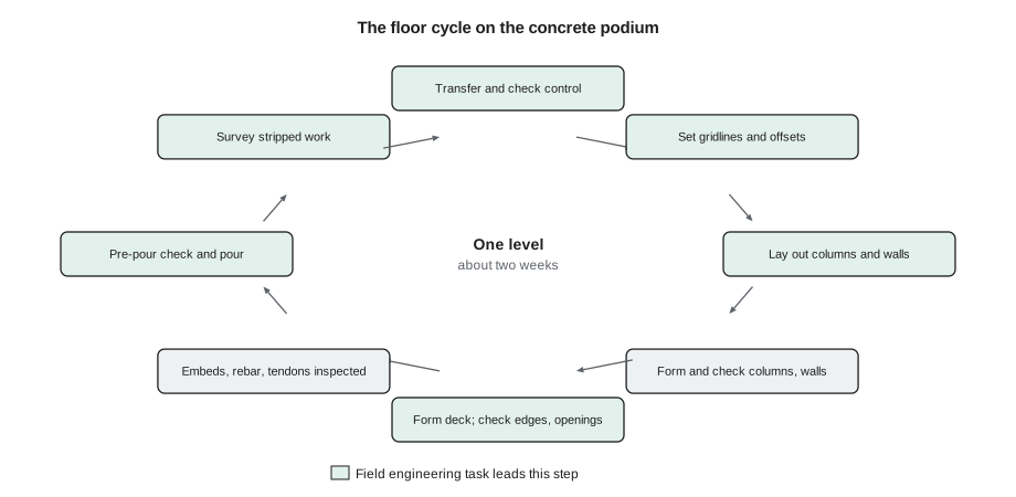
On a concrete podium the work on each level follows a cycle. Control is transferred up and checked; gridlines and offset lines are set on the new deck; columns and walls are laid out, formed and checked; the deck above is formed, its edges, openings, steps and embeds are laid out and checked; reinforcing and post-tensioning are placed and inspected; and the deck is poured. The field engineer's work is concentrated at the start of each step and in the checks before each pour. Delays in layout or checking delay the whole cycle.
Columns and walls
Columns and walls are laid out from offset lines on the slab below. For each column, the field engineer marks the column centre or corners, or a reference offset, and the formwork crew builds forms to those marks. Wall layout marks one face of the wall, usually with a second parallel line as a reference offset, plus the ends, openings and any steps. After forming, the field engineer checks position at the base, plumb, size and the height to the underside of the deck above.
Plumbness matters because a column that leans carries its error up to the next level. If the next column is laid out from the slab below, the error is corrected; if it is laid out by measuring up from the column below, the error accumulates. That is one reason for transferring control to each level independently rather than following the structure. After stripping, many contractors survey the columns of each level to confirm that they meet the specified tolerance and to provide an as-built record.
# Plumbness survey of level 1 podium columns after stripping (mm, project tolerance illustrative)
import math
height = 4500                       # level 1 to level 2, mm
allow = min(6 * height / 3000, 25)  # project tolerance: 6 mm per 3 m of height, 25 mm maximum
# offset of the column middle at the top relative to the base, (east, north) in mm
cols = {"B/2": (3, -2), "B/5": (-5, 4), "C/3": (8, 6), "D/5": (2, 1), "E/7": (-4, -9), "F/8": (1, 3)}
print(f"Allowed lean over {height} mm: {allow:.0f} mm")
for c, (de, dn) in cols.items():
    lean = math.hypot(de, dn)
print(f"{c:4s} lean {lean:4.1f} mm (1:{height/lean:.0f}) {'OK' if lean <= allow else 'OUT - report'}")Allowed lean over 4500 mm: 9 mm B/2 lean 3.6 mm (1:1248) OK B/5 lean 6.4 mm (1:703) OK C/3 lean 10.0 mm (1:450) OUT - report D/5 lean 2.2 mm (1:2012) OK E/7 lean 9.8 mm (1:457) OUT - report F/8 lean 3.2 mm (1:1423) OK
Four of the six columns are comfortably within the project tolerance of 9 mm over the 4.5 m height. Columns C/3 and E/7 lean just over it. Mei reports both to the structural engineer with the survey data. Small exceedances like these are often accepted by the engineer after checking that the eccentricity does not matter structurally, but that is the engineer's decision, not the contractor's. The survey also tells the formwork foreman that the bracing method used on those columns needs attention before the next level.
The tolerance in the example is the project's own. Concrete tolerances for plumb, position and level come from the project specification, which usually adopts a standard such as CSA A23.1 in Canada or ACI 117 in the United States, sometimes with tighter values for particular elements. Lesson 6 looks at how these tolerances combine.
Elevated slabs
Elevated slabs bring several layout tasks together. The deck formwork must be at the right elevation, allowing for any specified camber; the slab edge must be in the right place, because the envelope will be fixed to it; openings for stairs, shafts and services must be in the right place and the right size; and steps, depressions for wet areas or thicker toppings, drops and beams must be formed correctly.
Slab edges deserve particular care. On Larkspur Commons the window wall and cladding at the podium are attached to the slab edges, and the cladding system can absorb only a limited variation in edge position. Mei therefore surveys the edge forms before each pour and the cast edges afterwards, so that the cladding subcontractor can plan its anchors. Lesson 6 explains how to compare the slab edge tolerance with the cladding system's adjustment range.
Camber is an upward curve built into formwork or steel beams so that the element deflects to roughly level under load. Post-tensioned slabs, like the level 3 transfer slab at Larkspur Commons, may also move as the tendons are stressed. The structural drawings say whether camber is required and how much. The field engineer sets deck elevations accordingly, records the elevations before and after stressing and stripping, and reports unexpected movement. Deflection after stripping and long-term creep mean that a slab poured perfectly level may not stay level; finishes such as floor toppings and partitions must allow for that.
| Deck item | What the field engineer checks before the pour |
|---|---|
| Deck elevation | Elevation at grid points and midspans, including any specified camber |
| Slab edge | Position relative to gridlines, edge form height, cast-in anchors for cladding |
| Openings | Position, size, edge forms, protection and labelling |
| Steps and depressions | Location and depth for wet areas, balconies, mechanical rooms |
| Embeds and sleeves | Position, type and fixing (lesson 7) |
| Control transfer openings | Small openings for plumbing control to the next level, protected from concrete |
| Post-tensioning | Tendon profiles, anchor positions and conflicts with sleeves (with the post-tensioning supplier) |
Concrete cores, slipforms and jumpforms
Elevator and stair cores are often built ahead of the floors, using self-climbing jumpforms or, on taller buildings, continuously moving slipforms. On Larkspur Commons the two-storey podium core is formed conventionally, but on high-rise projects the core can be several floors ahead of the slabs, and its position, plumb and twist are surveyed continuously as it rises. Elevator shafts have tight tolerances on plumb and size, because elevator rails and doors must fit. Elevator installers usually survey the shaft themselves before installing rails and may refuse a shaft that is out of tolerance, so the field engineer surveys shafts as they are built and shares the results.
Openings in core walls for doors, corridors, ducts and slab connections must align with the floors that will connect to them later. Embedded plates or couplers for slab-to-core connections are a classic source of problems on jumpform jobs, because they must be set several days or weeks before the slab they serve is formed. Careful layout and an embed register (lesson 7) are essential.
Steel erection
Steel buildings are fabricated to precise dimensions in a shop and assembled on site, so the field engineer's role shifts from laying out forms to checking that the steel fits the foundations and is erected plumb and true. The key checks are anchor bolts and base plate elevations before erection (lesson 4), column plumbness during erection, and the elevation and alignment of beams that will support slabs, cladding or equipment.
Steel erection tolerances come from the codes of standard practice: in Canada the CISC Code of Standard Practice for Structural Steel together with CSA S16, and in the United States the AISC Code of Standard Practice. A commonly cited column plumbness tolerance is 1 in 500 of the height between connections, with limits on the total out-of-plumb of exterior columns over the building height. The steel erector is responsible for plumbing the frame; the field engineer or a surveyor typically checks it before the connections are completed and before decks or cladding make adjustments difficult.
On Larkspur Commons, the steel elements are small: the retail canopy, two steel stair towers and steel beams at the storefront. Even so, the canopy must align with the storefront glazing and the stairs must meet each landing at the right elevation, so Mei surveys each element before its connections are finalized.
Wood-frame layout
Above the podium, Larkspur Commons is built in light wood frame: stud walls, floor joists and sheathing. Wood framing is laid out differently from concrete. The framing crew typically snaps wall lines on each subfloor from control and gridlines provided by the field engineer, then builds walls flat on the deck and stands them up. Layout errors show up as walls that do not stack over the walls below, shear walls in the wrong place, or openings that do not line up with the windows above.
Wall stacking is important structurally. In a multi-storey wood building, load-bearing walls, shear walls and their hold-down rods must stack over each other so that loads flow down to the podium. The field engineer sets a consistent set of control lines on each floor, transferred from the podium control, and checks critical walls before sheathing and before the next floor is framed. Many projects use prefabricated wall panels, which arrive built to the shop drawings and must sit on accurate layout (lesson 8).
Allowing for wood shrinkage
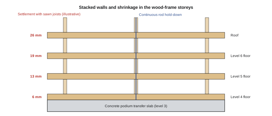
Wood shrinks as it dries, mostly across the grain. A wood-frame building settles as its plates, joists and rim boards dry from their moisture content at installation to their moisture content in service. The settlement accumulates up the building, so the top of a four-storey wood frame can be noticeably lower relative to elements that do not shrink, such as a concrete elevator core, a steel stair, masonry veneer, plumbing risers or the podium itself. The field engineer needs to understand the expected movement so that interfaces are built with the right gaps and the elevations are set correctly.
The example estimates the shrinkage for Larkspur Commons using an illustrative coefficient. Real designs use the engineer's figures, which depend on species, grade, moisture content and the floor system.
# Expected shrinkage of the four wood-frame floors above the podium (mm, illustrative coefficients)
coef = 0.0020            # dimensional change across the grain per 1 % change in moisture content
mc_install, mc_service = 19, 11   # % moisture content at installation and in service
per_floor = {            # horizontal (cross-grain) wood per floor, mm
    "bottom plate": 38, "double top plate": 76, "sawn floor joist or rim": 286,
}
cross_grain = sum(per_floor.values())
s_floor = cross_grain * coef * (mc_install - mc_service)
print(f"Cross-grain wood per floor: {cross_grain} mm -> shrinkage {s_floor:.1f} mm per floor")
total = 0
for name in ["Level 4 floor", "Level 5 floor", "Level 6 floor", "Roof"]:
    total += s_floor
    print(f"{name:13s} settles about {total:4.1f} mm relative to the podium slab")
# Same building with engineered joists and rims, which shrink very little
eng = (38 + 76) * coef * (mc_install - mc_service) * 4
print(f"With engineered floor joists and rims, the roof settles about {eng:.0f} mm")Cross-grain wood per floor: 400 mm -> shrinkage 6.4 mm per floor Level 4 floor settles about 6.4 mm relative to the podium slab Level 5 floor settles about 12.8 mm relative to the podium slab Level 6 floor settles about 19.2 mm relative to the podium slab Roof settles about 25.6 mm relative to the podium slab With engineered floor joists and rims, the roof settles about 7 mm
With sawn joists and plates installed at 19 % moisture content and drying to 11 %, each storey settles about 6 mm and the roof settles about 26 mm relative to the podium. Using engineered floor joists and rims, which are manufactured dry and shrink very little, reduces the roof settlement to about 7 mm. The design team specified engineered joists for Larkspur Commons for this reason. Even so, the remaining shrinkage must be allowed for at the elevator, where the shaft is concrete, at the steel stairs, at plumbing risers and at the window and cladding joints.
Practical consequences for field engineering include setting the elevator landing sills and stair landings with the designed allowance, checking that slip joints and gaps at risers and cladding are built as detailed, and recording the elevations of key points on each floor when framed and again later, so that actual movement can be compared with the prediction. Some designers specify that floors be framed slightly high at the interfaces so that they settle to the correct elevation. The field engineer follows the design and records what was done.
Building code changes have encouraged taller wood buildings. The 2020 National Building Code of Canada introduced encapsulated mass timber construction up to 12 storeys, and British Columbia adopted similar provisions; light wood frame is generally limited to six storeys for residential buildings. Mass timber shrinks much less than light frame across the floor zone, but it brings its own layout challenges, such as precise connections and tight tolerances for prefabricated panels (CON-240).
Elevations through the building
Getting elevations right is as important as getting positions right. Each level has a design elevation for the top of structure and a finished floor elevation. Field engineers transfer elevations up the building from the benchmarks, usually by measuring up a column or the core with a tape from a known mark and checking with a level loop on each floor. Over several floors, small errors and structural movements accumulate, so the field engineer compares each new floor's elevation with its design value rather than with the floor below.
Floor-to-floor heights matter to many trades: stairs must have equal risers, elevator doors must align, curtain wall or window units are made for a particular height, and services run in ceiling spaces with little spare room. A floor that comes out 20 mm low can force a non-compliant stair riser or a cut window frame. When a floor is out of tolerance, the field engineer reports it promptly so the design team can decide how to absorb the difference.
Common mistakes
MistakeLaying out each column by measuring up from the column below.
InsteadTransfer control to each level independently and lay out from offset lines on the new deck.
MistakeDeciding that a small exceedance of the plumbness tolerance does not matter.
InsteadReport it to the structural engineer with the survey data; acceptance is the engineer's decision.
MistakeSetting elevated deck forms level when camber is specified.
InsteadFollow the structural drawings for camber and record elevations before and after stressing and stripping.
MistakeIgnoring wood shrinkage at interfaces with concrete or steel.
InsteadBuild the designed gaps and allowances at elevators, stairs, risers and cladding, and record movement.
MistakeComparing each new floor's elevation with the floor below.
InsteadCompare each floor with its design elevation from the benchmarks so that errors do not accumulate.
Summary and key terms
- Each structural level follows a cycle in which field engineering starts each step and closes it with a check.
- Columns and walls are laid out from offset lines on the slab below and checked for position, plumb and height.
- Plumbness surveys after stripping provide records and early warning; exceedances go to the structural engineer.
- Elevated slabs need checks of elevation, camber, edges, openings, steps, embeds and post-tensioning before pouring.
- Cores and elevator shafts have tight tolerances and are surveyed continuously as they rise.
- Steel is fabricated precisely, so checks focus on anchor bolts, base plates, plumbness and beam elevations.
- Wood-frame walls must stack, and shrinkage accumulates up the building; engineered joists reduce it.
- Elevations should be checked against design values on every floor so that errors do not accumulate.
- Floor cycle
- The repeating sequence of layout, forming, checking and pouring or framing for each level.
- Plumbness
- The degree to which a column or wall is vertical, often expressed as a ratio of lean to height.
- Camber
- An upward curve built into a beam or slab so that it deflects to the intended shape under load.
- Slab edge
- The perimeter of a floor slab, to which the envelope is often attached.
- Jumpform
- A self-climbing formwork system that raises a core wall one level at a time.
- Code of standard practice
- An industry document that defines practices, including erection tolerances, for structural steel.
- Wall stacking
- Placing load-bearing and shear walls directly above those below so that loads flow down.
- Wood shrinkage
- The reduction in size of wood, mainly across the grain, as it dries.
Practice problems
Work each problem on paper first, then reveal the answer to check.
Why should control be transferred to each level independently?
Show answer
So that errors in the structure below are not carried up into the new layout.
In the plumbness example, which columns were out of tolerance and what happened?
Show answer
C/3 and E/7; Mei reported them to the structural engineer with the survey data.
Why does slab edge position matter?
Show answer
The envelope is attached to the slab edge and the cladding system can absorb only limited variation.
Why do elevator installers survey shafts before installing rails?
Show answer
Shafts must meet tight plumb and size tolerances for rails and doors to fit.
What commonly cited ratio is used for steel column plumbness?
Show answer
1 in 500 of the height between connections.
Why must wood-frame walls stack?
Show answer
So that gravity loads and shear wall forces flow directly down to the podium.
In the shrinkage example, how much did the roof settle with sawn joists and with engineered joists?
Show answer
About 26 mm with sawn joists and about 7 mm with engineered joists.
Name three interfaces where wood shrinkage must be allowed for.
Show answer
Elevator shaft and landings, steel stairs, plumbing risers, cladding and window joints.
Lesson quiz · 5 questions
Score 60% or more to complete this lesson.
Create a free account to save your progress, take quizzes and earn a certificate.