
CMPUT-411 · Lesson 5 of 12 · 32 min
Projection and the viewing pipeline
After the view matrix has placed the camera at the origin, the renderer must turn three-dimensional camera-space positions into two-dimensional screen positions. This is projection. It decides how much of the world the camera sees, how objects shrink with distance, and how depth is stored for visibility tests. This lesson derives the orthographic and perspective projection matrices, explains clip space, the perspective divide and normalized device coordinates, follows the viewport transform to pixels, and examines why depth precision is uneven and how reversed-Z fixes much of the problem. AI-350 (lesson 1) describes the pinhole camera model from the vision side, where the goal is the reverse: recovering 3D information from images.
The pinhole camera and perspective
A pinhole camera admits light through a single point, the centre of projection, onto an image plane. A scene point at camera-space position \((x, y, z)\), with the camera looking down the negative z axis, projects onto an image plane at distance d in front of the eye at \(x' = d\,x/(-z)\) and \(y' = d\,y/(-z)\). Division by depth is the essence of perspective: objects twice as far away appear half as large, parallel lines receding from the viewer converge to vanishing points, and the projection is not affine, because it does not preserve ratios of distances. Renaissance painters such as Brunelleschi and Alberti worked out the geometry of linear perspective in the fifteenth century; graphics computes it with matrices.
The camera's field of view determines how much of the scene is visible. A vertical field of view of \(\theta\) corresponds to an image plane at distance \(d = 1/\tan(\theta/2)\) if the image extends from −1 to 1 vertically. Typical values are 60 to 90 degrees for games, wider for driving and racing games that convey speed, and narrower for telephoto effects. The aspect ratio, width divided by height, scales the horizontal extent. A field of view that is too wide distorts shapes near the image edges, and one that does not match the viewer's actual angle to the screen can cause discomfort, which is why games let players adjust it.
The view frustum
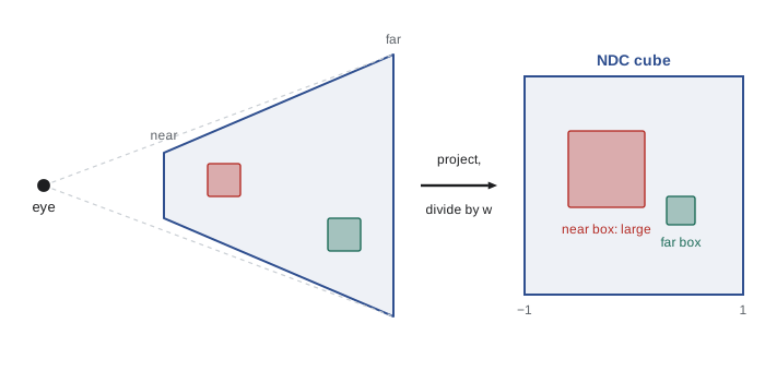
A real camera cannot see infinitely near or far, and a renderer must limit the depth range to store depth with finite precision. The visible region is the view frustum, a truncated pyramid bounded by the near and far clipping planes and four side planes through the eye and the edges of the image. Geometry outside the frustum is clipped or culled. The near plane cannot be at zero, because projection divides by depth, and, as we will see, depth precision depends strongly on how close it is.
Orthographic projection
Orthographic (parallel) projection discards depth for the image position: points project straight onto the image plane along parallel lines, so objects keep their size regardless of distance. It is used for engineering and architectural drawings, CAD views, two-dimensional games, user interfaces, shadow maps for directional lights (lesson 8) and isometric games. The orthographic projection matrix maps a box with left, right, bottom, top, near and far bounds \(l, r, b, t, n, f\) to the normalized cube. It is simply a scale and translation in each axis, an affine map, so w stays 1.
The perspective projection matrix
Perspective requires division by depth, which no affine matrix can perform. Homogeneous coordinates solve this: the projection matrix copies \(-z\) into the w component, and the hardware divides x, y and z by w afterwards. With vertical field of view \(\theta\), \(f = 1/\tan(\theta/2)\), aspect ratio a, and near and far distances n and f (written \(z_n\) and \(z_f\) below to avoid confusion), the classic OpenGL perspective matrix is
The first two rows scale x and y by the field of view and aspect ratio; the last row sets \(w = -z\), the distance in front of the camera. The third row is chosen so that, after division by w, depth maps the near plane to −1 and the far plane to +1. The result after the matrix is clip space, a four-dimensional homogeneous space in which the frustum test becomes simple: a point is inside the frustum exactly when \(-w \le x, y, z \le w\). Clipping is performed in clip space, before division, because there the planes are linear and points behind the eye (with negative w) can be handled correctly; dividing first would flip them through the eye and produce wild artefacts. Lesson 6 implements polygon clipping.
Dividing by w gives normalized device coordinates (NDC), a cube from −1 to 1 in x and y. Graphics APIs differ in the depth range: OpenGL uses −1 to 1, while Direct3D, Vulkan, Metal and WebGPU use 0 to 1, which changes the third row of the matrix; and Vulkan's NDC y axis points down. Libraries provide projection functions for each convention, and porting renderers between APIs often begins with these differences. Finally, the viewport transform maps NDC to window coordinates in pixels: \(x_w = (x_{ndc} + 1)\,W/2\), \(y_w\) similarly (flipped if pixel rows count downward), and depth to the range stored in the depth buffer.
# Perspective and orthographic projection (OpenGL conventions: camera looks
# down -z, NDC cube from -1 to 1), perspective divide and viewport mapping.
import numpy as np
def perspective(fovy_deg, aspect, near, far):
    f = 1 / np.tan(np.radians(fovy_deg) / 2)
    return np.array([[f / aspect, 0, 0, 0],
                     [0, f, 0, 0],
                     [0, 0, (far + near) / (near - far), 2 * far * near / (near - far)],
                     [0, 0, -1, 0]])
def ortho(l, r, b, t, n, f):
    return np.array([[2 / (r - l), 0, 0, -(r + l) / (r - l)],
                     [0, 2 / (t - b), 0, -(t + b) / (t - b)],
                     [0, 0, -2 / (f - n), -(f + n) / (f - n)],
                     [0, 0, 0, 1]])
W, H = 1280, 720
P = perspective(60, W / H, 0.1, 100.0)
def to_pixels(M, p):
    clip = M @ np.append(p, 1.0)
    ndc = clip[:3] / clip[3]                         # perspective divide
    x = (ndc[0] + 1) / 2 * W                        # viewport transform
    y = (1 - ndc[1]) / 2 * H                        # pixel rows grow downward
    return clip[3], ndc, (x, y)
print(" view-space point        w     NDC (x, y, z)            pixel")
for p in [(0, 0, -5), (1, 1, -5), (1, 1, -10), (1, 1, -50), (0, 0, -0.1), (0, 0, -100)]:
    w, ndc, (x, y) = to_pixels(P, p)
    print(f"{str(p):18} {w:7.2f}   ({ndc[0]:6.3f}, {ndc[1]:6.3f}, {ndc[2]:6.3f})   ({x:7.1f}, {y:6.1f})")
O = ortho(-8, 8, -4.5, 4.5, 0.1, 100)
print("orthographic: (1, 1, -5) and (1, 1, -50) ->",
tuple(round(float(v), 1) for v in to_pixels(O, (1, 1, -5))[2]), tuple(round(float(v), 1) for v in to_pixels(O, (1, 1, -50))[2]))view-space point w NDC (x, y, z) pixel (0, 0, -5) 5.00 ( 0.000, 0.000, 0.962) ( 640.0, 360.0) (1, 1, -5) 5.00 ( 0.195, 0.346, 0.962) ( 764.7, 235.3) (1, 1, -10) 10.00 ( 0.097, 0.173, 0.982) ( 702.4, 297.6) (1, 1, -50) 50.00 ( 0.019, 0.035, 0.998) ( 652.5, 347.5) (0, 0, -0.1) 0.10 ( 0.000, 0.000, -1.000) ( 640.0, 360.0) (0, 0, -100) 100.00 ( 0.000, 0.000, 1.000) ( 640.0, 360.0) orthographic: (1, 1, -5) and (1, 1, -50) -> (720.0, 280.0) (720.0, 280.0)
The table shows perspective at work. The point (1, 1) at depth 5 lands about 125 pixels right of and above the image centre; at depth 10 it is half as far from the centre, and at depth 50 one tenth. The w column is the distance in front of the camera. The near-plane point has NDC depth −1 and the far-plane point +1, but look at the intermediate depths: a point at 5 units, only 5 per cent of the way to the far plane, already has NDC depth 0.96. Most of the depth range is spent near the camera. The orthographic projection, by contrast, puts the two points at depths 5 and 50 at the same pixel.
Depth precision and z-fighting
After the perspective divide, stored depth is proportional to \(1/z\) plus a constant, not to z itself. This is not an accident: \(1/z\) varies linearly across a projected triangle in screen space, which makes depth interpolation exact and cheap in the rasterizer. But it means depth precision is concentrated near the near plane. With a near plane at 0.1 and a far plane at 1,000, half of the depth range is used within 0.2 units of the camera. Far away, many different depths round to the same stored value, and two nearly coplanar surfaces, such as a decal on a wall or overlapping road markings, flicker as pixels randomly show one or the other. This artefact is called z-fighting.
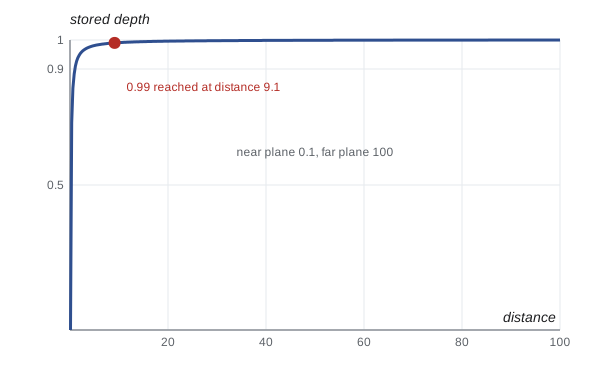
The most effective fix for z-fighting is to push the near plane out as far as the scene allows, because precision depends on the ratio of far to near and especially on the near distance. Moving the near plane from 0.1 to 1 improves distant precision about tenfold, while moving the far plane barely matters. Other remedies include a polygon offset or depth bias for decals and shadow maps, logarithmic depth buffers written by the shader, and, best of all on modern hardware, reversed-Z.
Floating-point numbers have their own uneven distribution: they are densest near zero. In a standard 0-to-1 depth buffer stored as 32-bit floats, distant objects map near 1, where floats are sparse, so the two nonuniformities compound. Reversing the mapping, so that the near plane maps to 1 and the far plane to 0, makes them cancel: distant depths land near zero, where floats are dense. Reversed-Z with a 32-bit floating-point depth buffer gives nearly uniform relative precision across the range and even allows an infinitely distant far plane. It requires a depth range of 0 to 1 (native in Direct3D, Vulkan, Metal and WebGPU, and available in OpenGL 4.5 through clip control), a projection matrix with the near and far roles swapped, and a reversed depth comparison.
# Depth precision: the smallest depth difference a depth buffer can resolve at
# distance d, for a 24-bit fixed-point buffer, a 32-bit float buffer, and a
# 32-bit float buffer with reversed Z (near maps to 1, far maps to 0).
import numpy as np
near, far = 0.1, 1000.0
def z_std(d):  return far / (far - near) * (1 - near / d)          # 0 at near, 1 at far
def z_rev(d):  return near / (far - near) * (far / d - 1)          # 1 at near, 0 at far
def resolve(zfun, d, step):
    h = 1e-4 * d
    slope = abs(zfun(d + h) - zfun(d - h)) / (2 * h)                # dz / dd
    return step(zfun(d)) / slope
fixed24 = lambda z: 2.0 ** -24
float32 = lambda z: float(np.spacing(np.float32(z)))
print("distance   24-bit fixed   float32 standard   float32 reversed")
for d in (1, 10, 100, 500, 900):
    a = resolve(z_std, d, fixed24); b = resolve(z_std, d, float32); c = resolve(z_rev, d, float32)
    print(f"{d:7} m   {a:10.2e} m   {b:12.2e} m     {c:12.2e} m")
print(f"fraction of the [0, 1] standard depth range used by the first 1 m: {z_std(1.0):.4f}")distance 24-bit fixed float32 standard float32 reversed
1 m 5.96e-07 m 5.96e-07 m 7.45e-08 m
10 m 5.96e-05 m 5.96e-05 m 9.31e-07 m
100 m 5.96e-03 m 5.96e-03 m 5.82e-06 m
500 m 1.49e-01 m 1.49e-01 m 1.82e-05 m
900 m 4.83e-01 m 4.83e-01 m 7.37e-06 m
fraction of the [0, 1] standard depth range used by the first 1 m: 0.9001The numbers make the case. With the standard mapping, resolution degrades with the square of distance: a fraction of a micrometre at 1 metre, but about 15 centimetres at 500 metres and about half a metre at 900 metres, enough for a decal or road marking to flicker against the surface beneath it. The standard float buffer is no better than 24-bit fixed point, because its extra precision sits near zero, where no distant depths land. With reversed-Z the same 32-bit float buffer resolves a few hundredths of a millimetre at 500 metres, an improvement of about four orders of magnitude at long range. The last line shows the root cause: in the standard mapping the first metre in front of the camera uses about 90 per cent of the depth range.
Culling and level of detail
Projection also enables culling, skipping work for geometry the camera cannot see. View-frustum culling tests each object's bounding volume against the six frustum planes and skips objects entirely outside; with a scene graph or bounding volume hierarchy, whole subtrees are rejected at once. Back-face culling skips triangles facing away from the camera, which for closed objects are always hidden: after projection, a triangle's winding order in screen space reveals its facing, so the rasterizer can discard back faces using the sign of the same signed area used in lesson 2. Occlusion culling skips objects hidden behind others, using depth from the previous frame, hardware occlusion queries or software rasterization of large occluders. Level of detail selects simpler versions of distant objects, based on their projected size, so that triangles stay larger than a few pixels.
| Technique | Skips | Typical test |
|---|---|---|
| Frustum culling | Objects outside the view volume | Bounding sphere or box against six planes |
| Back-face culling | Triangles facing away from the camera | Sign of screen-space signed area (winding) |
| Occlusion culling | Objects hidden behind others | Depth buffer from the previous frame, hierarchical depth, occlusion queries |
| Small-feature and detail culling | Objects smaller than a few pixels | Projected bounding-sphere size |
| Level of detail | Unneeded triangles on distant objects | Projected size or screen-space error |
Worked examples
Worked problem
Projecting a point
With a 90-degree vertical field of view and an aspect ratio of 1, where does the camera-space point (2, 1, −4) land in NDC x and y?
Show solution
- \(f = 1/\tan 45° = 1\), so the first two rows give clip x = 2 and clip y = 1.
- The last row gives \(w = -z = 4\).
- Divide: \(x_{ndc} = 2/4 = 0.5\), \(y_{ndc} = 1/4 = 0.25\).
Answer: NDC (0.5, 0.25): halfway to the right edge and a quarter of the way to the top.
Worked problem
Viewport transform
Map NDC (0.5, 0.25) to pixels in a 1920 by 1080 window whose rows count downward from the top.
Show solution
- \(x_w = (0.5 + 1)/2 \times 1920 = 1440\).
- \(y_w = (1 - 0.25)/2 \times 1080 = 405\).
Answer: Pixel (1440, 405).
Worked problem
Depth at mid-range
With near 1 and far 100 and an OpenGL-style matrix, what NDC depth does a point 10 units away have?
Show solution
- Clip z: \(\frac{101}{-99}(-10) + \frac{200}{-99} = 10.202 - 2.020 = 8.182\); w = 10.
- NDC z: \(8.182/10 = 0.818\).
Answer: About 0.82: a point one tenth of the way into the depth range uses about 91 per cent of the −1 to 1 interval.
Common mistakes
MistakeSet the near plane as small as possible "to be safe".
InsteadPush the near plane out as far as the scene allows; depth precision depends mostly on it.
MistakeClip triangles after dividing by w.
InsteadClip in homogeneous clip space so points behind the eye are handled correctly.
MistakeAssume all graphics APIs share the same NDC conventions.
InsteadCheck the depth range (−1 to 1 or 0 to 1) and y direction for each API and use matching projection functions.
MistakeStore depth linearly in z for easy interpolation.
InsteadHardware interpolates 1/z linearly in screen space; use reversed-Z or logarithmic depth for better precision instead.
MistakeUse a wide field of view to show more without considering distortion.
InsteadWide angles stretch shapes near the edges; let users adjust the field of view.
Summary and key terms
- Perspective divides by depth, so distant objects shrink and parallel lines converge.
- The view frustum, bounded by near, far and side planes, is the visible volume.
- Orthographic projection is affine; perspective projection puts depth into w and relies on the divide.
- Clip space tests visibility as \(-w \le x, y, z \le w\), and clipping happens there before division.
- NDC conventions differ by API: depth −1 to 1 in OpenGL, 0 to 1 in Direct3D, Vulkan, Metal and WebGPU.
- Stored depth is proportional to 1/z, concentrating precision near the camera and causing z-fighting far away.
- Reversed-Z with floating-point depth balances precision across the range; pushing out the near plane helps most.
- Projection
- Mapping three-dimensional points to a two-dimensional image.
- View frustum
- The truncated pyramid of space visible to a perspective camera.
- Field of view
- The angle subtended by the visible scene, usually given vertically.
- Clip space
- Homogeneous coordinates after the projection matrix and before division by w.
- Perspective divide
- Division of x, y and z by w that produces normalized device coordinates.
- Normalized device coordinates
- A cube from −1 to 1 in x and y that is independent of the output resolution.
- Viewport transform
- The mapping from normalized device coordinates to window pixel coordinates.
- Z-fighting
- Flickering between nearly coplanar surfaces because their depths round to the same value.
- Reversed-Z
- Mapping the near plane to depth 1 and the far plane to 0 to pair with floating-point precision.
- Back-face culling
- Discarding triangles that face away from the camera.
Practice problems
Work each problem on paper first, then reveal the answer to check.
What is f for a 60-degree vertical field of view?
Show answer
\(1/\tan 30° = 1.732\).
Why can the near plane not be at zero distance?
Show answer
Projection divides by depth, and depth precision collapses as near approaches zero.
What does the last row of a perspective matrix do?
Show answer
It copies the negated camera-space z into w.
What is the clip-space condition for a point to be inside the frustum?
Show answer
\(-w \le x, y, z \le w\).
Which APIs use a 0 to 1 NDC depth range?
Show answer
Direct3D, Vulkan, Metal and WebGPU.
Why is depth stored as a function of 1/z?
Show answer
Because 1/z interpolates linearly in screen space, so the rasterizer can interpolate it exactly.
Name two remedies for z-fighting.
Show answer
Push the near plane out; use reversed-Z; apply a depth bias for decals.
Why does reversed-Z help floating-point depth buffers?
Show answer
Distant depths map near 0, where floating-point values are densest.
What reveals whether a projected triangle is back-facing?
Show answer
Its winding order in screen space, the sign of its signed area.
Under orthographic projection, does an object's size change with distance?
Show answer
No.
Lesson quiz · 5 questions
Score 60% or more to complete this lesson.
Create a free account to save your progress, take quizzes and earn a certificate.