
CMP-315 · Lesson 9 of 12 · 26 min
Serial communication II: SPI and I²C
A UART needs no clock wire, but it pays for that with tight timing tolerances and low speed. For chips on the same board, a shared clock is cheap, and two synchronous serial buses dominate. The serial peripheral interface, SPI, uses separate data lines in each direction and a chip-select line per device, and runs at tens of megabits per second. The inter-integrated circuit bus, I²C, uses only two shared wires for any number of devices, with addresses and acknowledgements built into the protocol, at a few hundred kilobits per second. Between them they connect almost every sensor, memory, display controller, converter and power-management chip in embedded systems. This lesson explains both, how to choose between them, how to size I²C pull-up resistors from the bus capacitance, how to estimate transaction times, and how to make both buses robust.
On the NS-4, the radar module streams raw frames to the microcontroller over SPI, and a temperature sensor and a 32 KB ferroelectric memory share an I²C bus. Two problems wait for Jonah. The NS-5 will classify vehicles from radar frames on the node, which needs eight times the SPI throughput. And field units occasionally lock up the I²C bus after a brownout, so that the temperature reads fail until the next full power cycle.
SPI: signals and transfers
SPI connects one controller to one or more peripherals with four signals: a serial clock driven by the controller; controller-out peripheral-in, carrying data to the peripheral; controller-in peripheral-out, carrying data back; and an active-low chip select for each peripheral. Older documents call the controller the master and the peripheral the slave, and the data lines MOSI and MISO. The controller pulls one chip select low, toggles the clock, and on each clock edge both sides shift one bit out and one bit in. SPI is therefore inherently full duplex: every transfer exchanges bytes in both directions, and to read, the controller must send something, often zeros or a dummy byte.
SPI has no protocol beyond this. There are no addresses, no acknowledgements and no error checks; the meaning of the bytes is defined entirely by each peripheral's datasheet. A typical peripheral expects a command byte, sometimes followed by an address, and then data in or out while chip select remains low. Raising chip select ends the transaction and often triggers an action, such as starting a conversion or committing a write.
| Mode | Clock polarity (CPOL) | Clock phase (CPHA) | Clock idles | Data sampled on |
|---|---|---|---|---|
| 0 | 0 | 0 | Low | Rising edge |
| 1 | 0 | 1 | Low | Falling edge |
| 2 | 1 | 0 | High | Falling edge |
| 3 | 1 | 1 | High | Rising edge |
The four SPI modes combine clock polarity, whether the clock idles high or low, with clock phase, whether data are sampled on the first or second edge of each clock cycle. Modes 0 and 3 are the most common. A wrong mode often appears to almost work, with data shifted by one bit, so that values come out doubled or halved or with the top bit missing. Bit order is another setting: most devices send the most significant bit first, unlike a UART. Word size, usually 8 or 16 bits, and the minimum delays between chip select and the first clock edge complete the configuration.
SPI speed and throughput
SPI clocks of 10 to 50 MHz are common, limited by the peripheral, the microcontroller's SPI block and, above all, the board. At high clock rates, the round-trip delay through the controller's output, the trace, the peripheral's clock-to-output delay and back must fit inside half a clock period for the controller to sample the returned bit correctly. A peripheral with a 15 ns clock-to-output delay and a total trace and buffer delay of 10 ns limits reads to about 20 MHz. Writes are less constrained because the data travel with the clock.
Worked problem
SPI throughput for the NS-5 radar
The radar module sends frames of 2,048 samples of 16 bits each, 20 times per second today. The NS-5 classifier needs 160 frames per second. The SPI clock is 8 MHz, and each frame transfer has 20 µs of overhead for chip select, a command and DMA setup. What fraction of the bus does each rate use, and what clock would the NS-5 need to keep the bus below 50 percent busy?
Show solution
- \[ t_{\text{frame}} = \frac{2048 \times 16\ \text{bits}}{8\ \text{MHz}} + 20\ \mu\text{s} = 4.096 + 0.020 = 4.116\ \text{ms}\]
- At 20 frames per second the bus is busy 20 × 4.116 = 82 ms per second, 8.2 percent.
- At 160 frames per second it would be busy 659 ms per second, 66 percent, too close to saturation.
- \[ 160 \Big(\frac{32768}{f} + 20\ \mu\text{s}\Big) \le 0.5 \ \to\ f \ge \frac{32768 \times 160}{0.5 - 0.0032} = 10.6\ \text{MHz}\]
Answer: The present link uses 8.2 percent of the bus. The NS-5 needs an SPI clock of at least 10.6 MHz to stay below half load; Jonah proposes 16 MHz, within the radar module's 20 MHz limit, giving 33 percent load.
Throughput also depends on how the processor feeds the bus. Writing each byte from a polling loop leaves gaps between bytes while the code checks flags; at 16 MHz a byte takes only 0.5 µs, so even a short loop overhead halves the rate. DMA, as lesson 7 explained, keeps the shift register busy continuously. Many controllers also support quad SPI, with four data lines, for external flash memories, multiplying throughput by four for memory-mapped code or data.
/* Read one radar frame by SPI with DMA. The controller must transmit to receive, so a
   second DMA channel sends a constant dummy byte while the first collects the samples. */
static uint16_t frame[2048];
static const uint16_t dummy = 0;

void radar_read_frame(void)
{
    gpio_clear(RADAR_CS);
    spi_send16(SPI1, RADAR_CMD_READ_FRAME);
    dma_setup(DMA_RX_CH, &SPI1->DR, frame, 2048, DMA_MINC | DMA_16BIT | DMA_TCIE);
    dma_setup(DMA_TX_CH, &SPI1->DR, &dummy, 2048, DMA_16BIT);   /* no MINC: same word */
    spi_enable_dma(SPI1);
}

void DMA_RX_IRQHandler(void)               /* frame complete */
{
    dma_clear_flags(DMA_RX_CH);
    while (SPI1->SR & SPI_SR_BSY) { }       /* wait for the last bits to finish */
    gpio_set(RADAR_CS);
    frame_ready = 1;
}
I²C: two wires, many devices
I²C uses two lines, serial clock SCL and serial data SDA, shared by every device on the bus. Both lines are open-drain: devices can only pull them low, and pull-up resistors return them high. This wired-AND arrangement means any device can hold a line low without conflict, which the protocol uses for acknowledgements, clock stretching and arbitration between controllers. Each peripheral has a 7-bit address, set by its manufacturer and often partly by pins, so up to about 112 devices can share a bus after reserved addresses. Standard mode runs at 100 kHz, fast mode at 400 kHz and fast-mode plus at 1 MHz.
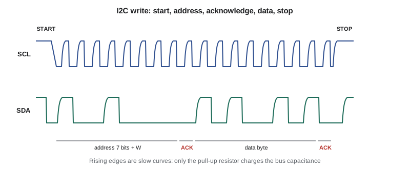
A transaction begins with a start condition: SDA falls while SCL is high. Normally SDA may change only while SCL is low, so a change while SCL is high is a unique marker. The controller then sends the 7-bit address and a direction bit, 0 for write and 1 for read. On the ninth clock, the addressed peripheral pulls SDA low to acknowledge; if no device responds, SDA stays high, a not-acknowledge, which tells the controller the device is absent or busy. Data bytes follow, each acknowledged by the receiver. A read usually begins with a write of the register address, then a repeated start, which is a start without a preceding stop, and the address again with the read bit. The controller acknowledges every byte it reads except the last, then sends a stop condition: SDA rises while SCL is high.
Pull-up resistors and rise time
Because I²C lines are pulled high only by resistors, rising edges are exponential curves whose time constant is the pull-up resistance times the total bus capacitance, made up of each device's pin capacitance, the traces and any cable. The I²C specification defines rise time from 30 percent to 70 percent of the supply, which for an RC curve is 0.8473 times the time constant. It sets a maximum rise time of 1,000 ns in standard mode and 300 ns in fast mode, and a maximum bus capacitance of 400 pF. That gives an upper limit on the pull-up resistance. The lower limit comes from the current a device can sink while holding the line below the low-level threshold: at least 3 mA at 0.4 V in standard and fast modes.
Worked problem
Sizing the NS-4 I²C pull-ups
The NS-4's I²C bus runs at 400 kHz from 3.3 V. The microcontroller pin, temperature sensor, memory, a test connector and 12 cm of trace add up to about 120 pF. Find the allowed pull-up range and choose a value.
Show solution
- \[ R_{\min} = \frac{3.3 - 0.4}{3\ \text{mA}} = 967\ \Omega\]
- \[ R_{\max} = \frac{300\ \text{ns}}{0.8473 \times 120\ \text{pF}} = 2.95\ \text{k}\Omega\]
- A standard 2.2 kΩ lies in the range. Its rise time is 0.8473 × 2.2 kΩ × 120 pF = 224 ns, and it draws 3.3 V ÷ 2.2 kΩ = 1.5 mA whenever a line is held low.
Answer: Use 2.2 kΩ, which gives a 224 ns rise time with 76 ns of margin. The old board used 10 kΩ, which would give a rise time of over 1 µs, acceptable only in standard mode.
# I2C pull-up range versus bus capacitance, and the rise time of a chosen resistor
VDD, VOL, IOL = 3.3, 0.4, 3e-3
modes = {"standard 100 kHz": 1000e-9, "fast 400 kHz": 300e-9}
r_min = (VDD - VOL) / IOL
print(f"R_min = {r_min:.0f} ohm (sink-current limit, all capacitances)")
for cb_pf in (50, 120, 200, 400):
    cb = cb_pf * 1e-12
    row = f"Cb = {cb_pf:3d} pF:"
    for name, tr in modes.items():
        r_max = tr / (0.8473 * cb)
        ok = "ok" if r_max > r_min else "impossible"
        row += f"   {name}: R_max = {r_max/1000:5.2f} kohm ({ok})"
    print(row)
R = 2200
for cb_pf in (120, 200):
print(f"2.2 kohm at {cb_pf} pF: rise time {0.8473*R*cb_pf*1e-12*1e9:.0f} ns")R_min = 967 ohm (sink-current limit, all capacitances) Cb = 50 pF: standard 100 kHz: R_max = 23.60 kohm (ok) fast 400 kHz: R_max = 7.08 kohm (ok) Cb = 120 pF: standard 100 kHz: R_max = 9.84 kohm (ok) fast 400 kHz: R_max = 2.95 kohm (ok) Cb = 200 pF: standard 100 kHz: R_max = 5.90 kohm (ok) fast 400 kHz: R_max = 1.77 kohm (ok) Cb = 400 pF: standard 100 kHz: R_max = 2.95 kohm (ok) fast 400 kHz: R_max = 0.89 kohm (impossible) 2.2 kohm at 120 pF: rise time 224 ns 2.2 kohm at 200 pF: rise time 373 ns
The table shows why long or heavily loaded buses are hard. At 400 pF, the fast-mode limit falls to 885 Ω, below the 967 Ω sink-current limit, so no resistor works and the bus cannot run at 400 kHz. Options then include slowing to standard mode, splitting the bus with a buffer or multiplexer, using a bus accelerator that actively drives rising edges, or choosing devices rated for fast-mode plus, which can sink 20 mA. The pull-up current is also a cost on battery-powered nodes, although it flows only while a line is low, so its average depends on traffic.
I²C transaction time
I²C's simplicity costs time. Each byte takes nine clocks with its acknowledge, and every transaction adds addresses, register pointers and start, repeated-start and stop conditions. Peripherals may also hold SCL low, called clock stretching, while they prepare data, which pauses the controller. These overheads make transaction times worth estimating before a design relies on them.
# Approximate I2C transaction times: each byte costs 9 clocks, each start/stop about 1 clock
def i2c_time(f_scl, nbytes, nstarts=1):
    clocks = 9 * nbytes + nstarts + 1      # starts (including repeated) plus one stop
    return clocks / f_scl
cases = {
    "temperature read: addr+W, reg, rpt start, addr+R, 2 data": (4 + 1, 2),
    "memory write of a 64-byte record: addr+W, 2 addr bytes, 64 data": (67, 1),
    "memory read of 64 bytes: addr+W, 2 addr, rpt start, addr+R, 64 data": (68, 2),
}
for name, (nbytes, starts) in cases.items():
    t100 = i2c_time(100e3, nbytes, starts)
    t400 = i2c_time(400e3, nbytes, starts)
print(f"{name:66s} {1e6*t100:7.0f} us at 100 kHz {1e6*t400:6.0f} us at 400 kHz")temperature read: addr+W, reg, rpt start, addr+R, 2 data 480 us at 100 kHz 120 us at 400 kHz memory write of a 64-byte record: addr+W, 2 addr bytes, 64 data 6050 us at 100 kHz 1512 us at 400 kHz memory read of 64 bytes: addr+W, 2 addr, rpt start, addr+R, 64 data 6150 us at 100 kHz 1538 us at 400 kHz
A temperature read takes about 120 µs at 400 kHz, and writing a 64-byte record about 1.5 ms. Ferroelectric memory accepts writes at bus speed; an EEPROM on the same bus would add a 5 ms internal write cycle after each page, during which it ignores its address, and firmware must poll it with address-only transactions until it acknowledges again. The NS-4 writes one record per vehicle at worst a few times per second, so either memory is fast enough, but the ferroelectric part also tolerates far more write cycles, which matters for a counter that may write ten million records over its life.
Making I²C robust
The lock-up that Jonah is chasing is a well-known I²C failure. If the microcontroller resets in the middle of a read, perhaps from a brownout or the watchdog, a peripheral may be partway through sending a byte and holding SDA low for a 0 bit. The controller, freshly reset, sees SDA low and believes the bus is busy, or it tries to send a start condition and fails. The peripheral, which never saw the clocks finish, waits forever. Only a power cycle of the peripheral clears it, and the NS-4's sensor is powered from the always-on rail.
The standard cure is bus recovery at startup. Before enabling the I²C peripheral, firmware configures SCL as a GPIO output and SDA as an input, and toggles SCL up to nine times until SDA is released high. Each clock lets the stuck peripheral shift out one more bit; after at most eight data bits and the acknowledge slot, it releases SDA. Firmware then generates a stop condition by hand and hands the pins back to the I²C peripheral. Jonah adds this to the NS-4 boot sequence, and the field lock-ups stop.
/* I2C bus recovery: clock out a peripheral that is stuck holding SDA low. */
void i2c_bus_recover(void)
{
    gpio_mode(I2C_SCL, GPIO_OUT_OD);
    gpio_mode(I2C_SDA, GPIO_IN);
    for (int i = 0; i < 9 && !gpio_read(I2C_SDA); i++) {
        gpio_clear(I2C_SCL); delay_us(5);
        gpio_set(I2C_SCL);   delay_us(5);
    }
    /* generate a stop: SDA low then high while SCL is high */
    gpio_mode(I2C_SDA, GPIO_OUT_OD);
    gpio_clear(I2C_SDA); delay_us(5);
    gpio_set(I2C_SDA);   delay_us(5);
    gpio_mode(I2C_SCL, GPIO_AF_I2C);
    gpio_mode(I2C_SDA, GPIO_AF_I2C);
}
Other robustness measures matter too. Every I²C operation needs a timeout, so a missing or failed device produces an error, not a hung main loop; the NS-4's driver gives each transaction 10 ms. Not-acknowledge responses should be counted and reported. Devices with fixed addresses can collide, so address planning belongs in the schematic review. Long I²C runs off the board, for example to a sensor in another enclosure, pick up noise and add capacitance; differential bus extenders or a different interface are better there. Systems with several controllers on one bus rely on I²C's arbitration: a controller that sends a 1 but sees a 0 knows another controller is driving, and backs off. SMBus and PMBus, used in power supplies and battery packs, are closely related to I²C, adding timeouts, packet error checking and standardized commands.
Choosing between SPI and I²C
| Property | SPI | I²C |
|---|---|---|
| Wires | Clock, two data lines, plus one select per device | Two shared lines for all devices |
| Speed | Typically 1 to 50 MHz | 100 kHz, 400 kHz or 1 MHz |
| Duplex | Full duplex | Half duplex |
| Addressing | By chip-select line | 7-bit address in each transaction |
| Acknowledge and errors | None in the protocol | Acknowledge per byte, arbitration |
| Power | Push-pull drivers, low static power | Pull-up current while lines are low |
| Typical uses | Fast converters, displays, radios, flash memory | Sensors, configuration registers, small memories, power management |
SPI is the choice for throughput and simplicity of timing; I²C is the choice when pins are scarce and many slow devices share a bus. Many products use both, as the NS-4 does. A third family, single-wire buses and newer two-wire standards that add in-band interrupts and higher speeds, appears in some sensors and mobile designs, but the principles of addressing, acknowledgement and rise time carry over.
Common mistakes
MistakeConfiguring the wrong SPI mode and accepting data that look nearly right.
InsteadMatch CPOL, CPHA and bit order to the datasheet; check a known register, such as a device ID, at startup.
MistakeRaising SPI chip select when the DMA count finishes rather than when the shift register is idle.
InsteadWait for the busy flag to clear before ending the transaction.
MistakeChoosing I²C pull-ups by habit.
InsteadCompute the range from the sink current and the rise-time limit at the actual bus capacitance.
MistakeWriting I²C drivers with no timeouts.
InsteadGive every transaction a timeout and count not-acknowledge and timeout errors.
MistakeIgnoring a peripheral stuck mid-byte after a reset.
InsteadRun bus recovery, up to nine clocks and a stop, before enabling the I²C peripheral.
Summary and key terms
- SPI uses clock, two data lines and chip selects; it is full duplex, fast and protocol-free.
- SPI modes set clock polarity and phase; both ends must match.
- At high SPI clocks, round-trip delay limits read speed; DMA keeps the bus busy.
- I²C uses two open-drain lines with pull-ups, 7-bit addresses and per-byte acknowledgement.
- Pull-ups must lie between the sink-current limit and the rise-time limit set by bus capacitance.
- Each I²C byte costs nine clocks, plus start, stop and addressing overhead.
- Bus recovery, timeouts and error counting make I²C robust in the field.
- SPI
- Serial peripheral interface: a synchronous bus with separate data lines and chip selects.
- Chip select
- An active-low line that selects one SPI peripheral.
- CPOL and CPHA
- SPI clock polarity and phase, which together define the mode.
- I²C
- Inter-integrated circuit bus: a two-wire, addressed, open-drain synchronous bus.
- Open drain
- An output that can only pull low; a resistor pulls the line high.
- Acknowledge
- A low bit sent by the receiver on the ninth clock of each I²C byte.
- Repeated start
- A start condition sent without a stop, typically to change direction.
- Clock stretching
- A peripheral holding SCL low to pause the controller.
- Bus capacitance
- The total capacitance on an I²C line, which with the pull-up sets rise time.
Practice problems
Work each problem on paper first, then reveal the answer to check.
How long does a 4 KB transfer take over SPI at 20 MHz with no gaps?
Show answer
4,096 × 8 ÷ 20 × 10⁶ ≈ 1.64 ms.
An I²C bus at 400 kHz has 200 pF of capacitance. What is the largest pull-up for fast mode?
Show answer
300 ns ÷ (0.8473 × 200 pF) ≈ 1.77 kΩ.
Approximately how long does a 16-byte I²C write with a 1-byte register address take at 100 kHz?
Show answer
Address + register + 16 data = 18 bytes × 9 = 162 clocks, plus start and stop ≈ 164 clocks ≈ 1.64 ms.
Why might a peripheral hold SDA low indefinitely after the controller resets?
Show answer
It was partway through sending a 0 bit and is waiting for clocks that never came.
Lesson quiz · 5 questions
Score 60% or more to complete this lesson.
Create a free account to save your progress, take quizzes and earn a certificate.