
CMP-315 · Lesson 3 of 12 · 21 min
Embedded C and the toolchain
C remains the main language of microcontroller firmware. It compiles to compact, fast code, it lets the programmer place data at exact addresses and manipulate individual bits, and every microcontroller vendor supplies a C compiler, headers and examples. C++ is common on larger projects, and Rust is growing, but the concepts in this lesson apply to all of them: how firmware reaches hardware registers, why the volatile keyword exists, how to set and clear bits safely, how source files become a binary image in flash, and what happens between reset and main. Jonah has written C before, but only for programs that run on a laptop. Embedded C looks the same and behaves differently in a dozen small ways that matter.
The NS-4 firmware is about 38,000 lines of C, built with an open-source cross-compiler. A cross-compiler runs on one machine, Jonah's laptop, and produces code for another, the NS-4's microcontroller. The build uses vendor-supplied register headers, a linker script, start-up code and a small hardware abstraction layer that Maren's team wrote years ago. The first week of the rework is spent understanding that build.
Reaching hardware registers from C
Lesson 2 showed that peripherals are controlled through registers at fixed addresses. C reaches them through pointers. A pointer to a 32-bit unsigned integer at address 0x4001 0814 lets firmware read and write the GPIO output register of port A. Vendor headers wrap such addresses in structures, one structure per peripheral type, with a member for each register in address order, so that code reads naturally: GPIOA->ODR for the output data register of port A, USART2->BRR for the baud-rate register of UART 2. The structure layout must match the hardware exactly, including reserved gaps, which is why these headers are generated from the vendor's register descriptions rather than written by hand.
#include <stdint.h>

/* One peripheral type described as a structure of registers */
typedef struct {
    volatile uint32_t MODER;    /* 0x00 mode: input, output, alternate, analog */
    volatile uint32_t OTYPER;   /* 0x04 output type: push-pull or open-drain   */
    volatile uint32_t OSPEEDR;  /* 0x08 output speed                           */
    volatile uint32_t PUPDR;    /* 0x0C pull-up / pull-down                    */
    volatile uint32_t IDR;      /* 0x10 input data (read only)                 */
    volatile uint32_t ODR;      /* 0x14 output data                            */
    volatile uint32_t BSRR;     /* 0x18 bit set/reset (write only)             */
} GPIO_TypeDef;

#define GPIOA ((GPIO_TypeDef *)0x40010800u)

void led_on(void)  { GPIOA->BSRR = (1u << 5); }          /* set pin 5         */
void led_off(void) { GPIOA->BSRR = (1u << (5 + 16)); }   /* reset pin 5       */
int  door_open(void) { return (GPIOA->IDR >> 3) & 1u; }  /* read pin 3        */
The fixed-width types from stdint.h, such as uint8_t, uint16_t and uint32_t, are essential. The size of a plain int depends on the compiler and target, while a hardware register has an exact width. Embedded code uses fixed-width types for registers, protocol fields and anything stored in flash, and reserves plain int for loop counters and arithmetic where size does not matter.
Why volatile matters
An optimizing compiler assumes that memory changes only when the program writes it. If a loop reads the same variable repeatedly without writing it, the compiler may read it once and keep the value in a register. For ordinary variables that is a valid and valuable optimization. For a hardware status register, whose bits change when a byte arrives or a conversion finishes, it is a disaster: the loop waits forever on a stale copy. The volatile qualifier tells the compiler that every read and every write must actually happen, in program order, because something outside the program can observe or change the value.
Three kinds of object need volatile: memory-mapped peripheral registers; global variables shared between an interrupt handler and the main program; and variables changed by another processor or a DMA controller. Volatile does not make an operation atomic, and it does not by itself order accesses between different volatile objects with respect to the hardware on every architecture; lesson 7 deals with shared data and critical sections, where volatile is necessary but not sufficient. Overusing volatile on ordinary variables simply makes code slower.
volatile uint32_t ticks;               /* incremented by the timer interrupt */

void delay_ms(uint32_t ms)
{
    uint32_t start = ticks;            /* volatile: read from memory each time */
    while ((ticks - start) < ms) {
        /* wait; without volatile the compiler may hoist the read out of the loop */
    }
}
The subtraction in that loop deserves a second look. Because ticks and start are unsigned 32-bit values, ticks − start gives the correct elapsed count even after ticks wraps from 4,294,967,295 back to zero, since unsigned arithmetic in C is defined modulo 2³². Writing the test as ticks < start + ms would break at the wrap. At one tick per millisecond the counter wraps after about 49.7 days, a bug that appears only in units that have been running for seven weeks, which is exactly the kind of bug the NS-4 had in its first year.
Bit manipulation
Registers pack many fields into one word: a mode field of two bits per pin, an enable bit, a three-bit prescaler, a flag. Firmware must change one field without disturbing the others. The standard idioms use masks. To set bit n, OR the register with 1 shifted left by n. To clear it, AND with the complement of that mask. To toggle, XOR. To test, AND and compare with zero. To write a multi-bit field, clear the field with a mask, then OR in the new value shifted into position. This read-modify-write sequence takes three steps, so if an interrupt handler changes the same register in between, one change can be lost; that is why many peripherals provide separate set and clear registers, such as the GPIO bit set/reset register above, which change bits in a single write.
Worked problem
Writing a mode field
The GPIO mode register gives each pin a two-bit field: 00 input, 01 output, 10 alternate function, 11 analog. Pin 5 must become an output and pin 9 an alternate function, without changing other pins. The register currently reads 0x2840 0000. What value should be written?
Show solution
- Pin 5's field occupies bits 11 and 10; its mask is 0b11 shifted left by 10, or 0x0000 0C00.
- Pin 9's field occupies bits 19 and 18; its mask is 0b11 shifted left by 18, or 0x000C 0000.
- Clear both fields: 0x2840 0000 AND NOT 0x000C 0C00 = 0x2840 0000, since those bits were already zero.
- OR in 01 at bit 10 (0x0000 0400) and 10 at bit 18 (0x0008 0000).
Answer: Write 0x2848 0400. The other pins' modes, held in the bits 0x2840 0000, are preserved.
# Register field helpers, mirroring the C idioms
def set_field(reg, shift, width, value):
    mask = (1 << width) - 1
    return (reg & ~(mask << shift) & 0xFFFFFFFF) | ((value & mask) << shift)

def get_field(reg, shift, width):
    return (reg >> shift) & ((1 << width) - 1)

moder = 0x28400000
moder = set_field(moder, 2 * 5, 2, 0b01)   # pin 5 output
moder = set_field(moder, 2 * 9, 2, 0b10)   # pin 9 alternate function
print(f"MODER = 0x{moder:08X}")
for pin in (5, 9, 13, 14):
    print(f"pin {pin:2d} mode = {get_field(moder, 2 * pin, 2):02b}")

# A baud-rate register with a 12-bit mantissa and 4-bit fraction (divide by 16 oversampling)
f_bus, baud = 24_000_000, 115_200
div = f_bus / (16 * baud)
mant, frac = int(div), round((div - int(div)) * 16)
print(f"divider {div:.4f} -> mantissa {mant}, fraction {frac}, BRR = 0x{(mant << 4) | frac:04X}")MODER = 0x28480400 pin 5 mode = 01 pin 9 mode = 10 pin 13 mode = 10 pin 14 mode = 10 divider 13.0208 -> mantissa 13, fraction 0, BRR = 0x00D0
The baud-rate calculation at the end previews lesson 8. The program shows that pin 13 and 14 hold the original modes, 10 and 10, which were the bits already set in 0x2840 0000. Writing such helpers once, and testing them on a laptop as here, avoids a whole class of driver bugs.
From source to image: the toolchain
Building firmware is a pipeline. The preprocessor expands macros and include files. The compiler turns each C file into assembly and then an object file containing machine code and data in named sections, plus symbols and relocation records for addresses not yet known. The linker combines object files and libraries, decides where every section goes in the memory map according to a linker script, resolves the symbols and writes an executable, usually in ELF format with debug information. A final step extracts a raw binary or hex image that a programmer writes into flash. Alongside the image, the linker can produce a map file listing every function and variable with its address and size, the first place to look when flash or RAM runs short.
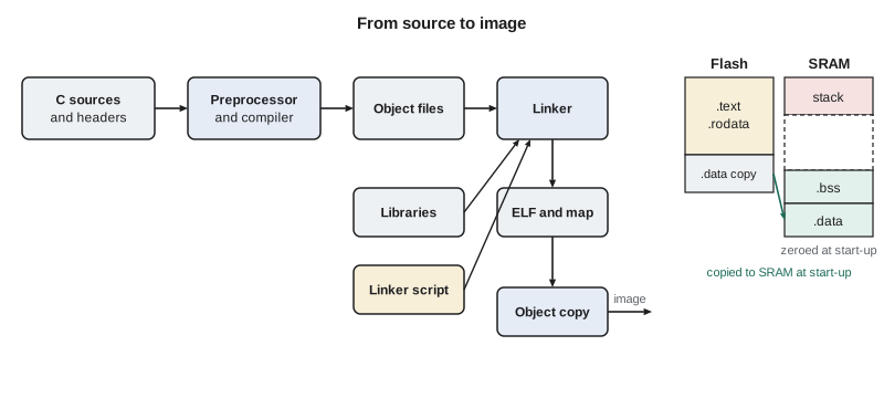
Four sections matter most. The text section holds machine code and goes in flash. Read-only data, such as constant tables and string literals, also goes in flash. The data section holds initialized global and static variables; because SRAM loses its contents when power is off, the initial values are stored in flash and copied into SRAM at start-up, so this section costs both flash and RAM. The bss section holds globals and statics with no initializer or a zero initializer; it costs only RAM, and start-up code clears it. The stack, and a heap if the design uses one, take the remaining RAM.
/* Excerpt from a linker script */
MEMORY
{
    FLASH (rx)  : ORIGIN = 0x08000000, LENGTH = 256K
    RAM   (rwx) : ORIGIN = 0x20000000, LENGTH = 64K
}
SECTIONS
{
    .isr_vector : { KEEP(*(.isr_vector)) } > FLASH
    .text       : { *(.text*) *(.rodata*) } > FLASH
    .data       : { _sdata = .; *(.data*) _edata = .; } > RAM AT > FLASH
    _sidata = LOADADDR(.data);
    .bss        : { _sbss = .; *(.bss*) *(COMMON) _ebss = .; } > RAM
    _estack = ORIGIN(RAM) + LENGTH(RAM);
}
Start-up code
Between reset and main, a short routine prepares the C environment. It runs before any C variable can be trusted, so it is often written in assembly or very careful C. It copies the data section's initial values from flash, starting at the load address the linker recorded, to their run addresses in SRAM. It fills the bss section with zeros. It may set up the floating-point unit, configure clocks and flash wait states, run C++ constructors for global objects, and finally call main. If main ever returns, which in firmware it should not, the start-up code loops forever or resets. A firmware engineer who understands this routine can debug the strange failures that happen before main, such as a hard fault caused by a stack placed outside RAM.
extern uint32_t _sidata, _sdata, _edata, _sbss, _ebss;
int main(void);
void system_init(void);       /* clocks and flash wait states */

void Reset_Handler(void)
{
    uint32_t *src = &_sidata, *dst = &_sdata;
    while (dst < &_edata) *dst++ = *src++;     /* copy .data from flash to RAM */
    for (dst = &_sbss; dst < &_ebss; ) *dst++ = 0u;   /* clear .bss */
    system_init();
    main();
    for (;;) { }                               /* main must not return */
}
Memory budgets and the map file
Flash and RAM are budgets, and the build should report how much of each is used. The NS-4's first rework build reports 182 KB of text and read-only data, 2.1 KB of initialized data and 41.3 KB of bss, with a 4 KB stack reserved. That leaves room in flash but less than it seems: the field-update scheme keeps two copies of the application, so the usable application area is half the flash, 128 KB, and the build no longer fits. Maren's first instruction to Jonah is to find what grew.
# Flash and RAM use from section sizes (bytes), as a build script might report them
sections = {"text": 176_400, "rodata": 9_970, "data": 2_150, "bss": 42_290}
stack = 4096
flash_total, ram_total = 256 * 1024, 64 * 1024
app_slot = flash_total // 2          # two application copies for safe updates

flash_used = sections["text"] + sections["rodata"] + sections["data"]   # data initializers live in flash
ram_used = sections["data"] + sections["bss"] + stack
print(f"flash used {flash_used/1024:6.1f} KB of {app_slot/1024:.0f} KB slot  ({100*flash_used/app_slot:.0f}%)")
print(f"RAM used   {ram_used/1024:6.1f} KB of {ram_total/1024:.0f} KB        ({100*ram_used/ram_total:.0f}%)")
print("over the slot by", round((flash_used - app_slot) / 1024, 1), "KB")flash used 184.1 KB of 128 KB slot (144%) RAM used 47.4 KB of 64 KB (74%) over the slot by 56.1 KB
The map file showed the culprit: a debugging printf with floating-point formatting pulled in about 40 KB of library code, used only by one diagnostic command. Replacing it with a small integer formatter brought the image down to about 144 KB, still over the slot, and removing two obsolete radar drivers brought it to 118 KB. Floating-point formatting, unused library features and duplicated lookup tables are the usual suspects when an embedded image is too large.
Habits of embedded C
A few habits prevent most embedded C bugs. Avoid dynamic memory allocation after start-up, because fragmentation can make an allocation fail after months of running, and the worst case is hard to bound. Size every buffer from a named constant and check every index. Know which operations are undefined behaviour in C, such as signed overflow, shifting by the width of the type or more, and reading an uninitialized variable, because the optimizer may assume they never happen and produce code that surprises you. Turn on all compiler warnings and treat them as errors. Prefer static functions and file-scope variables to global ones. And read the generated assembly for time-critical routines; it is the only way to know what the compiler actually did.
Common mistakes
MistakeLeaving volatile off a register pointer or an interrupt-shared variable.
InsteadThe compiler may cache the value or remove the access; declare hardware registers and shared variables volatile.
MistakeComparing timestamps as now < start + delay.
InsteadUse unsigned subtraction, now − start < delay, which stays correct when the counter wraps.
MistakeWriting a field with OR alone.
InsteadOR can set bits but not clear them; clear the field with an AND mask first, then OR in the new value.
MistakeForgetting that initialized globals use both flash and RAM.
InsteadThe data section's initial values sit in flash and are copied to RAM at start-up.
MistakeUsing malloc freely in long-running firmware.
InsteadAllocate statically or once at start-up; fragmentation and unbounded timing make heap use risky.
Summary and key terms
- Firmware reaches registers through pointers and vendor structures at fixed addresses.
- Fixed-width integer types match register and protocol widths exactly.
- volatile forces every access to happen; use it for registers and data shared with interrupts or DMA.
- Masks and shifts set, clear, toggle and write fields; set/clear registers avoid read-modify-write races.
- The toolchain compiles to object files, links them by a linker script into an ELF image and a map file.
- Start-up code copies .data to RAM, clears .bss, sets up clocks and calls main.
- Flash and RAM are budgets; the map file shows what uses them.
- Cross-compiler
- A compiler that runs on one machine and generates code for a different target processor.
- volatile
- A C qualifier telling the compiler that every access to an object must actually be performed.
- Read-modify-write
- Reading a register, changing some bits and writing it back; not atomic.
- Linker script
- A file that tells the linker where to place each section in the target memory map.
- .data section
- Initialized global and static variables, stored in flash and copied to RAM at start-up.
- .bss section
- Zero-initialized global and static variables, cleared in RAM at start-up.
- Map file
- A linker output listing the address and size of every symbol and section.
- Start-up code
- The routine that runs after reset to prepare memory and call main.
Practice problems
Work each problem on paper first, then reveal the answer to check.
Write the C expression that clears bit 7 of reg without changing other bits.
Show answer
reg &= ~(1u << 7);
A 3-bit prescaler field sits at bits 6 to 4. What mask selects it, and what value writes 5 into it?
Show answer
Mask 0x70; the value 5 << 4 = 0x50, written after clearing with reg &= ~0x70u.
Why does uint32_t elapsed = now − start give the right answer after a wrap?
Show answer
Unsigned arithmetic is modulo 2³², so the difference is correct as long as the true interval is under 2³² ticks.
A program has 10 KB of .data and 20 KB of .bss. How much flash and RAM do these sections use?
Show answer
.data uses 10 KB of flash and 10 KB of RAM; .bss uses 20 KB of RAM and no flash.
Lesson quiz · 5 questions
Score 60% or more to complete this lesson.
Create a free account to save your progress, take quizzes and earn a certificate.