
CMP-315 · Lesson 7 of 12 · 22 min
Interrupts, priorities and latency
A microcontroller must respond to events it cannot predict: a byte arriving on a serial port, a timer expiring, a conversion finishing, a vehicle entering the radar beam. It could poll, checking every status flag in a loop, but polling wastes energy, scales badly and responds slowly to whatever it checks last. Interrupts are the alternative. When a peripheral needs attention it raises an interrupt request; the core finishes its current instruction, saves enough state to resume later, and jumps to a handler for that source. When the handler returns, the interrupted code continues as if nothing had happened. Interrupts make embedded systems responsive and efficient, and they are also the source of their hardest bugs. This lesson covers how interrupt hardware works, how priorities and nesting decide who runs, how to calculate latency, how to write handlers, and how to share data between handlers and the main program safely.
The NS-4 has eleven active interrupt sources: the system tick, two radar input-capture channels, the radar SPI transfer-complete, two UART receivers, the I²C controller, the ADC's DMA completion, the low-power timer, the RTC alarm and the tamper switch. The timestamp bug of lesson 6 was, at heart, an interrupt priority bug. Before rewriting any handler, Maren asks Jonah to draw up a table of every source, how often it fires, how long its handler runs and what deadline it has.
The interrupt sequence
On a typical microcontroller core, an interrupt proceeds through a fixed sequence. A peripheral sets a pending bit in the interrupt controller. If that source is enabled and its priority is higher than whatever the core is currently doing, the core completes or abandons the current instruction, depending on its type, and starts exception entry. Hardware pushes a set of registers onto the stack, typically the program counter, status register, link register and the caller-saved general registers, so that a handler written as an ordinary C function can run without corrupting the interrupted code. The core reads the handler's address from the vector table, loads it into the program counter and begins executing. On return, a special instruction or return address pattern restores the saved registers and resumes the interrupted code.
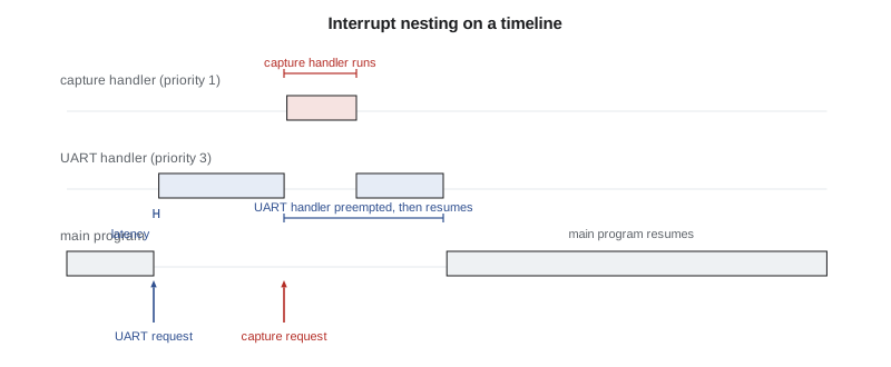
Cores designed for microcontrollers make this sequence fast and deterministic. Entry typically takes about 12 cycles; at 48 MHz that is a quarter of a microsecond. Two optimizations are common. Tail-chaining skips the full register restore and save when one handler finishes and another is already pending, going straight from one to the next. Late arrival lets a higher-priority interrupt that arrives during the register push take over the entry already in progress. Cores also stack registers lazily for the floating-point unit, saving them only if the handler actually uses floating point.
The interrupt controller, priorities and nesting
An interrupt controller tied closely to the core manages dozens or hundreds of sources. Each has an enable bit, a pending bit and a priority level. When several are pending, the highest priority runs first. If a request arrives while a handler is running, it preempts that handler only if its priority is strictly higher; otherwise it waits. This allows nesting: a critical handler can interrupt a less urgent one. Many controllers split each priority into a group priority, which decides preemption, and a subpriority, which only orders pending requests within the same group. A global mask register lets software block all interrupts below a chosen priority, or all interrupts entirely, for short critical sections.
Priorities should follow deadlines, not importance in some vaguer sense. The source with the shortest deadline relative to its handler length gets the highest priority, a rule related to rate-monotonic scheduling, which lesson 12 and CMP-440 discuss further. The old NS-4 firmware gave the modem's UART receive handler the highest priority because losing a modem byte meant a failed upload, and gave the radar detect interrupt a low priority because, in the original designer's words, 'the timestamp only needs to be within a millisecond'. But the modem handler could run for 400 µs while parsing a line, and the radar handler then started late. With input capture, the radar timestamps no longer depend on latency at all, but Jonah still reorders priorities so that short, urgent handlers come first.
| Source | Rate (worst case) | Handler time | Deadline | New priority |
|---|---|---|---|---|
| Radar input capture (two lanes) | 2 per second each, bursts of 4 | 3 µs | Before next capture overwrites, about 50 ms | 1 (highest) |
| Radar SPI transfer complete | 20 per second | 6 µs | Next frame, 50 ms | 2 |
| RS-485 UART receive | 11,520 bytes per second | 2 µs | Next byte, 87 µs | 2 |
| Modem UART receive (with DMA) | Idle-line event per message | 40 µs | Next message, about 1 ms | 3 |
| System tick | 1,000 per second | 1.5 µs | Next tick, 1 ms | 3 |
| I2C transfer events | About 200 per second during reads | 4 µs | Bus timeout, 10 ms | 4 |
| ADC DMA complete | 1 per second | 25 µs | Next block, 1 s | 5 |
| Tamper switch, RTC, low-power timer | Rare | Under 5 µs | Seconds | 6 (lowest) |
Interrupt latency
Interrupt latency is the time from the event to the first useful instruction of its handler. It includes the time for the peripheral to set its flag and for the request to synchronize to the core clock; the time to finish the current instruction, which for multi-cycle instructions such as divides or multiple-register loads can add tens of cycles; the exception entry; any flash wait states while fetching the vector and the first handler instructions; and, crucially, any time spent waiting for higher-priority handlers or for a section of code that has masked interrupts. The worst case is dominated by the last two terms, which firmware controls.
Worked problem
Worst-case latency of the RS-485 receive interrupt
At 115,200 baud, an RS-485 byte arrives every 86.8 µs, and the UART holds one received byte plus the one being shifted in, so the handler must read each byte within about one byte time. The core runs at 48 MHz. Synchronization and the longest instruction take up to 20 cycles, entry takes 12 cycles plus 2 wait states, and the longest section with interrupts masked is 15 µs, in the flash-write routine. The only higher-priority handler is the 3 µs radar capture, which can fire twice back to back. Is the deadline met?
Show solution
- \[ t_{\text{hw}} = \frac{20 + 12 + 2}{48\ \text{MHz}} = 0.71\ \mu\text{s}\]
- Higher-priority handlers can delay it by 2 × 3 µs = 6 µs, but the 15 µs masked section is worse, so the blocking term is 15 µs.
- \[ t_{\text{latency,max}} \approx 0.71 + 15 = 15.7\ \mu\text{s}\]
- Adding the handler's own 2 µs gives 17.7 µs, well inside the 86.8 µs byte time.
Answer: The deadline is met with a large margin. The 15 µs masked section is the biggest threat; if it grew to 90 µs, bytes would be lost.
Writing interrupt handlers
Good interrupt handlers are short. They acknowledge the source, move data between the peripheral and a buffer, record an event or timestamp, perhaps set a flag or post a message to a queue, and return. Anything slow, such as parsing a protocol line, writing flash, formatting text or computing a classification, belongs in the main loop or a task. A long handler increases the latency of every handler at its priority and below, and it is harder to test. The NS-4's old modem handler parsed complete lines and updated the configuration inside the interrupt; Jonah's version uses DMA to fill a buffer, takes a 40 µs idle-line interrupt to mark the end of a message, and leaves parsing to the main loop.
Handlers must clear the condition that caused them, usually by reading a data register or writing a flag-clear register. If they do not, the request stays pending and the handler runs again immediately after it returns, forever, starving everything below it. On some microcontrollers, the flag clear takes a few cycles to propagate through the peripheral bus, so clearing it as the last instruction can cause a spurious second interrupt; the safe habit is to clear early in the handler or read the register back after clearing.
#define RX_SIZE 256u                      /* power of two */
static volatile uint8_t  rx_buf[RX_SIZE];
static volatile uint16_t rx_head, rx_tail; /* head written by ISR, tail by main loop */
static volatile uint32_t rx_overruns;

void USART1_IRQHandler(void)              /* RS-485 receive */
{
    uint32_t sr = USART1->SR;
    if (sr & USART_SR_RXNE) {
        uint8_t b = (uint8_t)USART1->DR;   /* reading DR clears RXNE */
        uint16_t next = (uint16_t)((rx_head + 1u) & (RX_SIZE - 1u));
        if (next != rx_tail) { rx_buf[rx_head] = b; rx_head = next; }
        else                 { rx_overruns++; }
    }
}

int rx_get(uint8_t *out)                   /* called from the main loop */
{
    if (rx_tail == rx_head) return 0;
    *out = rx_buf[rx_tail];
    rx_tail = (uint16_t)((rx_tail + 1u) & (RX_SIZE - 1u));
    return 1;
}
Sharing data safely
When an interrupt handler and the main program share data, the main program can be interrupted between any two instructions. If it is halfway through updating a multi-word value, or through a read-modify-write of a shared variable, the handler may see or create an inconsistent state. A classic example is a 64-bit timestamp extended from a 32-bit counter: the main program reads the low word, the overflow interrupt fires and increments the high word, and the main program then reads the new high word with the old low word, producing a time about 71 minutes off. Another is a counter incremented by both the handler and the main loop with a non-atomic load, add, store sequence, which loses counts.
There are four standard remedies. First, design the data so that only one side writes each variable, as in the ring buffer above, where the handler owns the head and the main loop owns the tail. Second, use atomic operations: aligned 32-bit loads and stores are atomic on 32-bit cores, and many cores provide exclusive load and store instructions or atomic read-modify-write instructions. Third, protect a critical section by briefly masking interrupts, or better, raising the mask only to the priority of the handlers that share the data, so higher-priority handlers still run. Fourth, read a multi-word value twice and retry if it changed. Whatever the method, every shared variable must also be volatile, as lesson 3 explained, but volatile alone does not make an operation atomic.
static volatile uint32_t ovf_hi;          /* incremented by the timer overflow ISR */

uint64_t time_us(void)
{
    uint32_t hi, lo;
    do {
        hi = ovf_hi;
        lo = TIM2->CNT;                    /* 32-bit counter at 1 MHz */
    } while (hi != ovf_hi);                /* retry if an overflow happened in between */
    return ((uint64_t)hi << 32) | lo;
}
Masking interrupts is simple and correct but adds directly to worst-case latency, as the example showed. Critical sections should be a few instructions long, never contain loops of unknown length, and never call functions that might wait. The NS-4's flash-write routine was the 15 µs masked section; it cannot be shortened because the flash controller stalls bus reads during programming, but Jonah moves it so that it runs only between radar frames.
Polling, interrupts and DMA
Interrupts are not always the right tool. For events that occur at very high rates, such as ADC samples at 100 kHz or SPI bytes at several megabits per second, an interrupt per item would consume most of the processor; direct memory access is better. A DMA controller, configured by firmware with a source, destination, count and trigger, moves data between peripherals and memory without the core, and interrupts only when a block is complete or half complete. For events that occur rarely and are not urgent, polling a flag once per main-loop pass is simpler and has no shared-data hazards. And for very short waits, such as a few microseconds for a peripheral to become ready, polling is faster than the overhead of entering and leaving an interrupt.
# Processor load from interrupts versus DMA for the NS-4's main data flows
f_cpu = 48e6
entry_exit = 24          # cycles to enter and leave a handler
flows = {
    # name: (events per second, handler cycles per event if interrupt-driven)
    "RS-485 receive, 115200 baud": (11_520, 60),
    "radar SPI bytes, 20 frames x 2048 x 2 bytes": (81_920, 40),
    "ADC samples at 10 kHz": (10_000, 50),
}
dma_block_irqs = {"radar SPI bytes, 20 frames x 2048 x 2 bytes": 40,   # half and full per frame
                  "ADC samples at 10 kHz": 20}
for name, (rate, cyc) in flows.items():
    load_irq = rate * (cyc + entry_exit) / f_cpu
    line = f"{name:45s} interrupt per item: {100*load_irq:5.1f}% of CPU"
    if name in dma_block_irqs:
        load_dma = dma_block_irqs[name] * (200 + entry_exit) / f_cpu
        line += f"   with DMA: {100*load_dma:6.3f}%"
print(line)RS-485 receive, 115200 baud interrupt per item: 2.0% of CPU radar SPI bytes, 20 frames x 2048 x 2 bytes interrupt per item: 10.9% of CPU with DMA: 0.019% ADC samples at 10 kHz interrupt per item: 1.5% of CPU with DMA: 0.009%
An interrupt per radar byte would take about 11 percent of the processor and wake it 82,000 times a second; DMA reduces that to a few hundredths of a percent and lets the core sleep while the frame arrives. The RS-485 link, at 11,520 bytes per second, costs about 2 percent with one interrupt per byte, which is acceptable, and its messages are short and irregular, so an interrupt-driven ring buffer remains the simpler choice there.
Faults and exceptions
Interrupts share their machinery with exceptions raised by the core itself: hard faults from invalid memory accesses or illegal instructions, bus faults from accesses to unmapped addresses, usage faults such as division by zero when trapping is enabled, and memory-management faults from the protection unit. A default fault handler that loops forever leaves a field unit frozen until the watchdog resets it, with no clue to the cause. A better handler records the stacked program counter, the link register and the fault status registers in a reserved RAM area or flash, then resets. After the next boot, the firmware reports the record. Half of the NS-4 rework's eventual bug fixes were found this way during field trials.
Common mistakes
MistakeDoing slow work, such as parsing or flash writes, inside an interrupt handler.
InsteadKeep handlers short; move slow work to the main loop or a task, signalled by a flag or queue.
MistakeAssigning priorities by perceived importance.
InsteadAssign them by deadline relative to handler length; short, urgent handlers come first.
MistakeForgetting to clear the interrupt source.
InsteadAcknowledge or clear the flag in the handler, or it will fire again immediately and starve lower priorities.
MistakeSharing multi-word or read-modify-write data without protection.
InsteadUse single-writer designs, atomic operations, brief masked sections or read-retry loops.
MistakeMasking all interrupts for long sections.
InsteadEvery masked microsecond adds to worst-case latency; keep critical sections tiny or mask only lower priorities.
Summary and key terms
- An interrupt saves state, runs a handler from the vector table and resumes the interrupted code.
- Microcontroller cores enter handlers in about a dozen cycles and support tail-chaining and late arrival.
- The interrupt controller orders sources by priority; higher priorities preempt lower ones.
- Worst-case latency is dominated by masked sections and higher-priority handlers.
- Handlers should be short, clear their source and defer slow work.
- Shared data needs single-writer design, atomics, brief critical sections or read-retry, plus volatile.
- High-rate data flows belong to DMA; rare, non-urgent events can be polled.
- Interrupt
- A hardware signal that suspends the current code to run a handler.
- Interrupt service routine
- The handler function that runs in response to an interrupt.
- Vector table
- The table of handler addresses indexed by interrupt or exception number.
- Nesting
- A higher-priority interrupt preempting a running lower-priority handler.
- Interrupt latency
- The time from an event to the start of its handler.
- Critical section
- A short code region protected from interruption while it accesses shared data.
- Tail-chaining
- Moving directly from one handler to the next pending one without restoring and resaving registers.
- DMA
- Direct memory access: hardware that moves data between peripherals and memory without the core.
Practice problems
Work each problem on paper first, then reveal the answer to check.
A core needs 12 cycles for entry at 80 MHz, and the longest masked section is 8 µs. What is the worst-case latency, ignoring other handlers?
Show answer
12 ÷ 80 MHz = 0.15 µs; worst case ≈ 8.15 µs.
A UART at 921,600 baud with a one-byte buffer is serviced by interrupts. How long does the handler have per byte?
Show answer
10 bits ÷ 921,600 ≈ 10.9 µs.
Why is the ring buffer in this lesson safe without disabling interrupts?
Show answer
The handler writes only the head and the main loop writes only the tail; each index is a single aligned write.
An interrupt costs 70 cycles in total and fires 50,000 times per second on a 48 MHz core. What fraction of the CPU does it use?
Show answer
50,000 × 70 ÷ 48 × 10⁶ ≈ 7.3 percent.
Lesson quiz · 5 questions
Score 60% or more to complete this lesson.
Create a free account to save your progress, take quizzes and earn a certificate.