
CIV-440 · Lesson 5 of 12 · 22 min
Sheet pile and embedded walls
Gravity, cantilever and MSE walls are built from the bottom up: the ground is excavated, the wall is built, and the backfill is placed behind it. Embedded walls are built from the top down. Steel sheet piles, soldier piles with lagging, secant or contiguous bored piles and diaphragm walls are installed into the ground first, and the soil in front of them is then excavated. They stand because the part of the wall below the excavation level is pushed against the soil in front, mobilizing passive resistance, and, if the wall is tall, because anchors or struts hold it near the top. This lesson covers cantilever and anchored sheet pile walls, using the outfall of the new storm sewer on Kestrel Creek.
The storm sewer from the operations centre discharges to the creek downstream of the culvert. Its outfall structure needs a headwall, and the utility chamber beside it needs a deeper excavation against the bank. Borehole BH-9 at the outfall found loose to compact alluvial sand, \(\phi' = 32^\circ\), to 10 m, with the water table 1.5 m below the bank top, a thicker sand than elsewhere on the site. Both walls will be steel sheet piles: a cantilever wall retaining 3.0 m for the headwall, and an anchored wall retaining 5.0 m for the chamber.
Cantilever embedded walls
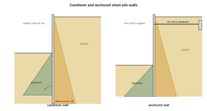
A cantilever sheet pile wall rotates about a point a little above its toe. Above that point, active pressure acts behind and passive pressure in front; below it, the pressures reverse, with passive pressure behind the wall and active in front. Blum's simplified method replaces the reversed pressures below the point of rotation by a single concentrated force \(R\) at a depth \(D_0\), where the toe would be. Taking moments about that point eliminates \(R\) and gives one equation for \(D_0\): the moment of the active pressure on the full height \(h + D_0\) equals the moment of the passive pressure on \(D_0\). The wall is then extended by about 20 % to provide the length over which \(R\) develops:
Safety is introduced either by dividing the passive coefficient by a factor, typically 1.5 to 2.0, or by increasing the embedment by a further 20 to 40 % with the full passive coefficient. The two approaches should not be confused, and should not both be omitted. The maximum bending moment occurs below the excavation level, where the shear force is zero. Cantilever sheet pile walls are economical only for retained heights up to about 4 to 5 m, because the moment grows with the cube of the height and the deflection with its fifth power.
Anchored walls and free earth support
A wall anchored near its top can retain much greater heights. If the embedment is just sufficient for the passive resistance in front to balance the thrust not carried by the anchor, the toe is free to rotate and the wall behaves as a beam simply supported by the anchor and the soil in front. This is the free earth support method. Taking moments about the anchor gives the embedment directly:
where \(\bar{z}_a\) and \(\bar{z}_p\) are the lever arms of the active and passive resultants about the anchor. Horizontal equilibrium then gives the anchor force, \(T = P_a - P_p\). The maximum moment is found at the point of zero shear between the anchor and the dredge line. Deeper embedment produces fixity at the toe, the fixed earth support condition, which reduces the moment and the anchor force but needs a longer pile.
Flexible walls redistribute pressure. Rowe's model tests in the 1950s showed that a flexible anchored wall in sand deflects between the anchor and the excavation level, arching transfers load to the stiffer anchor and toe zones, and the actual maximum moment is less than the free earth support value. Design manuals give moment reduction charts based on Rowe's flexibility number. Modern practice often uses beam-on-springs or finite element analyses instead, especially when deflections must be controlled near structures.
Worked problem
The outfall headwall: a cantilever sheet pile wall
The headwall wall retains 3.0 m of alluvial sand with \(\phi' = 32^\circ\), \(\gamma = 18\) kN/m³ above and \(\gamma' = 10\) kN/m³ below the water table at 1.5 m, with water at the same level on both sides below the dredge line. Use \(K_a = 0.307\) and \(K_p/1.5 = 2.17\). Find the embedment and the maximum moment.
Show solution
- Blum's equation, moments about the theoretical toe at depth \(D_0\), is solved numerically:
- \[D_0 = 4.20\ \text{m} \qquad D = 1.2(4.20) = 5.04\ \text{m} \qquad L = 3.0 + 5.04 = 8.04\ \text{m}\]
- The maximum moment occurs below the dredge line, at the point of zero shear:
- \[M_{max} \approx 70.9\ \text{kN·m/m}\]
Answer: An 8 m pile is needed to retain 3 m, which is typical: a cantilever wall in sand needs more than its retained height below the excavation. The team specifies 8.5 m piles to allow for scour of the creek bed in front of the wall.
Worked problem
The utility chamber: an anchored sheet pile wall
The chamber wall retains 5.0 m of the same sand, with a tie rod 1.0 m below the top connected to a deadman anchor far enough back to be outside the active wedge. Find the embedment by free earth support, the anchor force and the maximum moment.
Show solution
- Moments of the active and reduced passive pressures about the anchor, solved numerically:
- \[D = 2.70\ \text{m, specify } 1.2D = 3.24\ \text{m; pile length } 8.24\ \text{m}\]
- \[T = P_a - P_p = 37.6\ \text{kN/m} \;\Rightarrow\; 94\ \text{kN per tie rod at } 2.5\ \text{m}\]
- \[M_{max} = 60.3\ \text{kN·m/m at } 4.07\ \text{m depth}\]
Answer: The anchored wall retains two thirds more height with about the same pile length as the cantilever headwall and a smaller moment. The extra 20 % of embedment covers over-dredging and scour, and the anchor and its deadman must be designed for the anchor force with their own factor of safety.
The script solves both walls by numerical integration of the pressure diagrams, finds the embedments by bisection and locates the maximum moments.
# Sheet pile walls at the Kestrel Creek outfall: cantilever and anchored (free earth support)
from math import tan, radians
UNITS = "SI"
SI = UNITS == "SI"
L, F, P, MU = ("m", "kN/m", "kPa", "kN.m/m") if SI else ("ft", "lb/ft", "psf", "lb.ft/ft")
phi = 32.0
g, gsub, zw = (18.0, 10.0, 1.5) if SI else (115.0, 63.6, 5.0)       # moist and submerged unit weights; water table depth on the retained side
Ka = tan(radians(45 - phi / 2)) ** 2; Kp = tan(radians(45 + phi / 2)) ** 2; Kpd = Kp / 1.5
def sv(z):                       # vertical effective stress behind the wall (water table at zw)
    return g * z if z <= zw else g * zw + gsub * (z - zw)
def solve(h, D, anchor=None, n=600):
    """Net force and moment on a wall of retained height h embedded D, water level the same both sides below zw."""
    Fa = Ma = Fp = Mp = 0.0
    dz = (h + D) / n
    for i in range(n):
        z = (i + 0.5) * dz
        pa = Ka * sv(z)
        Fa += pa * dz; Ma += pa * dz * z
        if z > h:
            pp = Kpd * gsub * (z - h) if h >= zw else Kpd * (g * min(z - h, zw - h) + gsub * max(0, z - zw))
            Fp += pp * dz; Mp += pp * dz * z
    return Fa, Ma, Fp, Mp
print(f"Ka = {Ka:.3f}, Kp = {Kp:.2f}, Kp/1.5 = {Kpd:.2f} used for design")
# 1) cantilever wall: moment about the toe of the simplified (fixed-toe) method, then add 20 %
h1 = 3.0 if SI else 10.0
lo, hi = 0.1, 30.0
for _ in range(60):
    D = (lo + hi) / 2; Fa, Ma, Fp, Mp = solve(h1, D)
    zt = h1 + D
    if (Fa * zt - Ma) > (Fp * zt - Mp): lo = D       # active moment about the toe exceeds passive: embed deeper
    else: hi = D
D0 = D
print(f"\nCantilever, retained height {h1:g} {L}: D0 = {D0:.2f} {L}; design embedment 1.2 D0 = {1.2*D0:.2f} {L}; pile length {h1 + 1.2*D0:.2f} {L}")
# maximum moment at zero shear below dredge level
best = 0
for k in range(1, 600):
    z = h1 + D0 * k / 600; Fa, Ma, Fp, Mp = solve(h1, z - h1)
    if Fa - Fp <= 0: break
    best = max(best, Fa * z - Ma - (Fp * z - Mp))
print(f"  maximum bending moment about {best:.1f} {MU}")
# 2) anchored wall: free earth support, anchor at depth a
h2, a = (5.0, 1.0) if SI else (16.0, 3.0)
lo, hi = 0.1, 30.0
for _ in range(60):
    D = (lo + hi) / 2; Fa, Ma, Fp, Mp = solve(h2, D)
    if (Ma - Fa * a) > (Mp - Fp * a): lo = D          # moments about the anchor
    else: hi = D
Fa, Ma, Fp, Mp = solve(h2, D); T = Fa - Fp
print(f"\nAnchored, retained height {h2:g} {L}, anchor {a:g} {L} below the top: D = {D:.2f} {L}; specify {1.2*D:.2f} {L} ({h2 + 1.2*D:.2f} {L} long)")
print(f"  anchor force T = {T:.1f} {F}; with anchors at {2.5 if SI else 8.0} {L} spacing, {T*(2.5 if SI else 8.0):.0f} {'kN' if SI else 'lb'} per anchor")
Mmax = 0; zm = 0
for k in range(1, 2000):
    z = (h2 + D) * k / 2000; Fa_, Ma_, Fp_, Mp_ = solve(h2, max(z - h2, 0), n=400) if z > h2 else solve(z, 0, n=400)
    M = (Fa_ * z - Ma_) - (Fp_ * z - Mp_) - (T * (z - a) if z > a else 0)
    if abs(M) > abs(Mmax): Mmax, zm = M, z
print(f"  maximum moment {abs(Mmax):.1f} {MU} at {zm:.2f} {L} depth")
fy = 345e3 if SI else 50000 * 144                  # kPa | psf
S = abs(Mmax) / (0.65 * fy)
print(f" required section modulus at 0.65 fy: {S*1e6:.0f} cm3/m".replace("cm3/m", "cm3/m") if SI else f" required section modulus at 0.65 fy: {S*1728:.1f} in3/ft")Ka = 0.307, Kp = 3.25, Kp/1.5 = 2.17 used for design Cantilever, retained height 3 m: D0 = 4.20 m; design embedment 1.2 D0 = 5.04 m; pile length 8.04 m maximum bending moment about 70.9 kN.m/m Anchored, retained height 5 m, anchor 1 m below the top: D = 2.70 m; specify 3.24 m (8.24 m long) anchor force T = 37.6 kN/m; with anchors at 2.5 m spacing, 94 kN per anchor maximum moment 60.3 kN.m/m at 4.07 m depth required section modulus at 0.65 fy: 269 cm3/m
Reading the results and choosing a section
With an allowable bending stress of about 0.65 of the yield strength of 345 MPa steel, the anchored wall needs a section modulus of about 270 cm³/m, and the cantilever headwall a little more. These are light sections, but sheet piles in practice are selected also for driveability, for corrosion allowance and for stiffness, and the lightest sections can be damaged when driven through dense layers or cobbles. The team selects a medium-weight Z-section for both walls, with a corrosion allowance for a design life of 75 years in fresh water with road-salt runoff, and specifies vibratory installation with a check on vibrations at the culvert.
Deflection matters next to the culvert and the road. A cantilever wall of this height will deflect a few tens of millimetres at its top; the anchored wall much less. The team estimates both with a beam-on-springs model and sets a monitoring limit for the top of the headwall.
Anchors, deadmen and tiebacks
The anchor of a sheet pile wall can be a tie rod to a deadman, a continuous concrete beam or sheet pile wall buried behind the active wedge, or a grouted ground anchor drilled through the wall. A deadman works by passive resistance, so it must lie outside the active wedge of the wall and its own passive wedge must not overlap that of the wall: the usual rule places it behind a line drawn from the dredge level at the angle of the passive plane. Ground anchors, the subject of lesson 6, are drilled at an inclination and bonded in soil or rock beyond the failure wedge; their vertical component adds axial load to the wall.
Waling beams spread the anchor force along the wall. The tie rod, the waling and the connections are designed as structural elements, usually with a margin above the calculated force to allow for the uncertainty of the earth pressure distribution and for the loss of one anchor.
| Wall type | Typical use | Retained height | Water tightness | Notes |
|---|---|---|---|---|
| Cantilever sheet pile | headwalls, temporary cuts | up to about 4–5 m | good | large deflection |
| Anchored or braced sheet pile | waterfronts, excavations | 5–15 m | good | installation by vibration or impact |
| Soldier piles and lagging | excavations above water | 3–15 m | none | needs dewatering below the water table |
| Secant or contiguous piles | urban excavations | 5–20 m | secant good | stiff, low vibration |
| Diaphragm wall | deep basements | 10–30 m | good | often part of the permanent structure |
Practical points
- Check the effect of scour and over-excavation on the embedment, and add length for it.
- Introduce safety once: either a factor on \(K_p\) or extra embedment, as the method requires.
- Locate deadmen outside the active wedge and with their own passive wedge clear of the wall's.
- Choose sections for driveability, corrosion and stiffness as well as moment.
- Estimate and monitor deflection where the wall is near structures or roads.
Common mistakes
MistakeForgetting the 20 % extension of the embedment in Blum's method.
InsteadThe extension provides the length over which the toe reaction develops.
MistakeUsing the full passive coefficient and no extra embedment.
InsteadEither reduce \(K_p\) or increase the embedment; one of them is the factor of safety.
MistakePlacing a deadman inside the active wedge of the wall.
InsteadIt then moves with the wall and provides little resistance.
MistakeIgnoring the unbalanced water pressure when the water level behind the wall is higher than in front.
InsteadAdd the net water pressure; it can be the largest load on a waterfront wall.
Summary and key terms
- Embedded walls rely on passive resistance below the excavation, and on anchors or struts for greater heights.
- Cantilever walls: Blum's method gives \(D_0\) from moments about the toe; \(D = 1.2D_0\).
- Anchored walls: free earth support gives \(D\) from moments about the anchor and \(T = P_a - P_p\).
- Flexible walls carry less moment than calculated (Rowe); beam-on-springs and finite element methods are common.
- The outfall headwall needs 8 m piles to retain 3 m; the anchored chamber wall 8.2 m to retain 5 m, with 94 kN per tie rod.
- Sections are chosen for moment, driveability, corrosion and deflection.
- Embedded wall
- A wall installed into the ground before excavation, supported below the excavation by passive resistance.
- Sheet pile
- An interlocking steel section driven or vibrated into the ground to form a continuous wall.
- Dredge line
- The level of the ground in front of an embedded wall after excavation.
- Blum's method
- A simplified analysis of cantilever embedded walls that replaces the toe pressures by a concentrated force.
- Free earth support
- The condition of an anchored wall whose toe can rotate, analysed by moments about the anchor.
- Fixed earth support
- The condition of an anchored wall embedded deeply enough for its toe to be fixed.
- Deadman
- A buried block, beam or short wall that anchors a tie rod by passive resistance.
- Waling
- A horizontal beam that distributes anchor or strut forces along a wall.
Practice problems
Work each problem on paper first, then reveal the answer to check.
For a cantilever wall in sand, Blum's method gives \(D_0 = \) 3.6 m. What embedment would you specify, and why?
Show answer
\(D = 1.2(3.6) = 4.3\) m, plus an allowance for scour or over-excavation; the 20 % provides the length for the toe reaction.
An anchored wall has \(P_a = \) 150 kN/m and \(P_p = \) 95 kN/m at free earth support. Find the anchor force per tie rod at 3.0 m spacing.
Show answer
\(T = 55\) kN/m, 165 kN per rod.
Why does the maximum moment in a cantilever sheet pile wall occur below the dredge line?
Show answer
The shear force is zero where the passive resistance in front has grown to equal the total active thrust above, which happens some distance below the dredge line.
What does Rowe's moment reduction account for?
Show answer
The redistribution of earth pressure caused by the flexibility of the wall, which reduces the maximum moment below the free earth support value.
Lesson quiz · 5 questions
Score 60% or more to complete this lesson.
Create a free account to save your progress, take quizzes and earn a certificate.