
CIV-440 · Lesson 12 of 12 · 22 min
Capstone: the geotechnical design report
The calculations of the previous eleven lessons are now brought together in the geotechnical design report for the phase 3 works and the Ridgeway Road improvements. A design report is not a collection of calculations. It sets out what is to be built, what the ground is, what the design must achieve, how each element was designed and checked, what was assumed, what could go wrong and how construction will confirm the design or reveal that it must change. Its readers are the owner, the structural and civil designers who use its recommendations, the contractor who prices and builds from it, and the reviewer who checks it. This lesson assembles the report, and in doing so finds one problem that none of the individual calculations revealed.
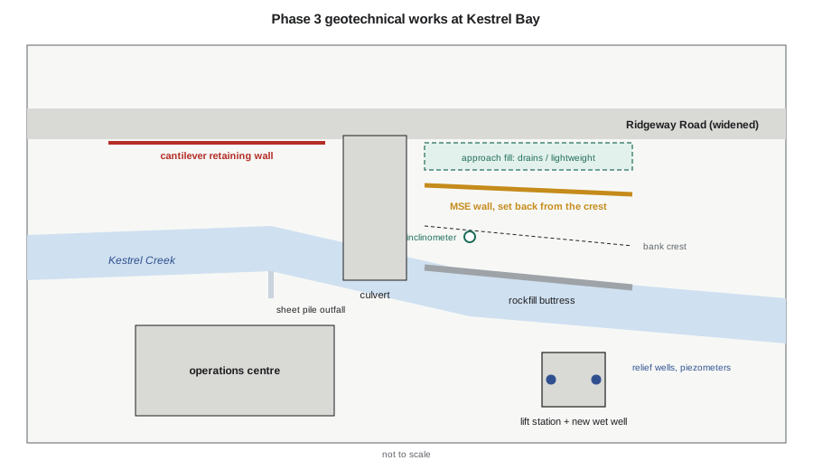
The structure of the report
Practice and the expectations of owners vary, but a geotechnical design report usually contains:
- An introduction: the project, the scope of the report and the documents it relies on.
- The site and the ground: geology, the investigation, the ground model, the groundwater and the characteristic parameters, with reference to the factual investigation report.
- The design basis: codes and standards, design life, loads and load combinations, factors of safety or resistance factors, performance criteria and the consequence class.
- The design of each element: method, assumptions, results and recommendations.
- Construction considerations: sequence, temporary works, dewatering, winter work, specifications and testing.
- Risks and monitoring: the geotechnical risk register, the instrumentation and the trigger levels and responses.
- Limitations: the extent of the investigation and the conditions under which the recommendations apply.
The report should be written so that a competent engineer who was not on the team can follow every recommendation back to its basis. The calculations are appended or kept on file, but the report states the key numbers.
The design basis
For the Kestrel Bay works, the design basis lists the National Building Code and the Canadian Foundation Engineering Manual for the site works and the lift station, the Canadian Highway Bridge Design Code (CSA S6) for the road retaining walls and the culvert, the City of Thunder Bay's engineering standards, the provincial occupational health and safety requirements for excavations, and the conservation authority's requirements for work near the creek. The design life is 75 years for the walls and the culvert and 50 years for the lift station. Limit states design is used with the load and resistance factors stated in each section, and slopes are designed to factors of safety of 1.5 for long-term conditions and 1.3 for the seasonal high water.
The ground model is the one developed in Soil Mechanics and refined in Foundation Engineering, with the additions of this course: the alluvial sand at the outfall, the piezometric readings in the creek bank and the seasonal water levels. Characteristic parameters are cautious estimates of the mean, not the lowest test values, and the report gives them in one table with their sources.
| Layer | Depth (m) | Unit weight | Strength | Other |
|---|---|---|---|---|
| Bank and site sand (SP-SM) | 0–4.0 | 18.0 / 19.8 kN/m³ | φ' = 34° | borderline frost-susceptible |
| Alluvial sand at the outfall | 0–10 | 18.0 kN/m³ | φ' = 32° | water table 1.5 m |
| Varved clay (CL) | 4.0–11.0 | 18.0 kN/m³ | su = 55 kPa; c' = 5 kPa, φ' = 27° | F4; Cc 0.316, cv 2.5 m²/yr |
| Till (SM), artesian | 11.0–15.5 | 21.5 kN/m³ | very dense | head 1.5 m below grade |
| Granular backfill | – | 20 kN/m³ | φ' = 32° | free-draining |
| MSE reinforced fill | – | 20 kN/m³ | φ' = 34° | select granular |
The design checks
Each element of the works is summarized with its governing checks, from the lessons of this course, as demand-to-capacity ratios so that a reader can see at a glance how close each is to its limit. The summary also includes the result of one more check, which the team ran while assembling the report.
The MSE wall of lesson 4 passed its external and internal checks, and the buttressed bank of lesson 9 passed its slope stability checks. But the wall stands on the bank, and the two had been analysed separately. When Priya Raman, reviewing the draft, asked for the global stability of the wall and the bank together, Sofia added the reinforced block to the slope model as a strip load on the bank top. With the wall face 4 m behind the crest, as in the preliminary layout, the factor of safety is 1.26 in spring and 1.44 in summer: both below the targets. Moving the wall 2 m further from the crest raises them to 1.41 and 1.60. The road alignment can accommodate the move by narrowing the boulevard on the far side, and the civil designer has agreed. This is the kind of interaction that an integrated report exists to catch.
Worked problem
Global stability of the MSE wall on the buttressed bank
Represent the 6.0 m MSE wall as a strip load of 120 kPa over its 4.5 m reinforced length on the top of the buttressed bank, and find the critical Bishop factors of safety for two setbacks of the wall face from the crest.
Show solution
- Using the slice model of lessons 8 and 9 with the buttress in place:
- \[\text{Setback 4 m: } F_{spring} = 1.26,\; F_{summer} = 1.44 \qquad \text{Setback 6 m: } F_{spring} = 1.41,\; F_{summer} = 1.60\]
Answer: The preliminary layout fails both targets; with the wall moved back to 6 m from the crest, both are met with margins of about 8 and 7 %. A strip load is a simplification of the real wall, and the final check is made in the slope stability program with the wall modelled as reinforced soil.
# Capstone: global stability of the MSE wall on the bank, limit state summary, trigger levels and the risk register
from math import tan, radians, sqrt
UNITS = "SI"
SI = UNITS == "SI"
L, P = ("m", "kPa") if SI else ("ft", "psf")
k = 1.0 if SI else 3.281                       # length scale: the US section is the same geometry in feet
gw = 9.81 if SI else 62.4
sand = dict(c=0.0, phi=34.0, g=19.0 if SI else 121.0)
clay = dict(c=5.0 if SI else 105.0, phi=27.0, g=18.0 if SI else 115.0)
Hb, y_int = 5.0 * k, 3.0 * k           # bank height, slope n:1, sand above elevation y_int, clay below
q, xq = (12.0 if SI else 250.0), 4.0 * k        # road surcharge starting 4 m | 13 ft behind the crest
OPT = dict(n=2.0, butt=0.0, drains=False)       # slope, buttress height above the toe, drains
rock = dict(c=0.0, phi=40.0, g=20.0 if SI else 127.0)
def ground(x):
    n = OPT["n"]; base = 0.0 if x <= 0 else (x / n if x <= n * Hb else Hb)
    bw = 4.0 * k                                 # buttress: flat top 4 m | 13 ft wide from the toe, then 1.5H:1V down to the bed
    if OPT["butt"] > 0 and -1.5 * OPT["butt"] < x <= bw + 0.0:
        top = OPT["butt"] if x >= 0 else OPT["butt"] + x / 1.5
        return max(base, top)
    return base
WATER = {"summer": (0.3, 2.0), "spring": (1.5, 0.5), "spring with drains": (0.3, 1.5)}   # water level at the bank face above the toe, depth below the crest far back
def phreatic(x, case):
    yf, db = WATER[case]; yf *= k; yb = Hb - db * k; xb = OPT["n"] * Hb + 6 * k
    if OPT["butt"] > 0 and x <= 4.0 * k: return min(0.3 * k, ground(x))   # free-draining rockfill: water at creek level
    if x <= 0: return min(yf, ground(x))
    y = yf + (yb - yf) * min(x / xb, 1.0)
    return min(y, ground(x))
def slices(xc, yc, R, case, N=60):
    out = []; dx = 2 * R / N
    for i in range(N):
        x = xc - R + (i + 0.5) * dx
        yb = yc - sqrt(max(R * R - (x - xc) ** 2, 0)); yt = ground(x)
        h = yt - yb
        if h <= 0: continue
        nat = 0.0 if x <= 0 else min(x / OPT["n"], Hb)   # natural ground below any buttress
        hr = max(0.0, yt - max(yb, nat)) if yt > nat else 0.0
        hs = max(0.0, min(yt, nat) - max(yb, y_int)); hc = max(0.0, h - hs - hr)
        W = (sand["g"] * hs + clay["g"] * hc + rock["g"] * hr) * dx + (q * dx if x >= OPT["n"] * Hb + xq else 0.0) + (QW * dx if OPT["n"] * Hb + SB <= x <= OPT["n"] * Hb + SB + LW else 0.0)
        u = max(0.0, phreatic(x, case) - yb) * gw
        soil = rock if yb >= nat and hr > 0 else (sand if yb >= y_int else clay)
        s = (x - xc) / R; cth = sqrt(1 - s * s)
        out.append((W, u, soil, s, cth, dx))
    return out
def fs_ordinary(sl):
    if sum(W * s for W, u, sm, s, ca, dx in sl) <= 0: return 99
    num = sum(sm["c"] * dx / ca + (W * ca - u * dx / ca) * tan(radians(sm["phi"])) for W, u, sm, s, ca, dx in sl)
    den = sum(W * s for W, u, sm, s, ca, dx in sl)
    return num / den if den > 0 else 99
def fs_bishop(sl):
    F = fs_ordinary(sl)
    if F >= 99 or F <= 0: return 99
    for _ in range(50):
        num = 0.0
        for W, u, sm, s, ca, dx in sl:
            tp = tan(radians(sm["phi"])); m = max(ca + s * tp / F, 0.2)
            num += (sm["c"] * dx + (W - u * dx) * tp) / m
        den = sum(W * s for W, u, sm, s, ca, dx in sl)
        Fn = num / den
        if abs(Fn - F) < 1e-5: break
        F = Fn
    return Fn if Fn > 0 else 99
def search():
    best = 99
    for i in range(-6, 19):
        for j in range(0, 15):
            xc, yc = i * 0.5 * k, Hb + j * 0.5 * k
            for d in (0, 2, 4, 6):
                sl = slices(xc, yc, yc + d * 0.5 * k, CASE)
                if len(sl) >= 5: best = min(best, fs_bishop(sl))
    return best

# 1) global stability: the MSE wall as a strip load on the buttressed bank, for two setbacks from the crest
QW, LW = (120.0 if SI else 2500.0), 4.5 * k       # reinforced block 6 m | 20 ft high, 4.5 m | 15 ft long
OPT.update(dict(n=2.0, butt=2.0 * k))
for SB in (4.0 * k, 6.0 * k):
    CASE = "spring"; Fs = search(); CASE = "summer"; Fu = search()
    print(f"MSE wall face {SB:.0f} {L} behind the crest: spring FS = {Fs:.2f} (1.3 required), summer FS = {Fu:.2f} (1.5 required)")
checks = [  # element, check, demand/capacity ratio (ca LSD utilization or us 1/FS ratio, from lessons 3 to 11)
    ("Cantilever wall", "sliding", 0.89 if SI else 1.5 / 1.85),
    ("Cantilever wall", "bearing", 0.48 if SI else 3.0 / 6.30),
    ("MSE wall", "geogrid rupture, bottom layer", 0.54 if SI else 0.55),
    ("MSE wall", "sliding of the block", 1.5 / 2.26 if SI else 1.5 / 2.24),
    ("Anchored outfall wall", "embedment (passive / 1.5)", 1 / 1.2),
    ("Wet well excavation", "basal heave (FS 1.5 required)", 1.5 / 3.26 if SI else 1.5 / 3.24),
    ("Wet well excavation", "clay plug uplift with relief wells (FS 1.3)", 1.3 / 1.53 if SI else 1.3 / 1.47),
    ("Creek bank with buttress", "spring water levels (FS 1.3)", 1.3 / 1.65),
    ("Creek bank with buttress", "summer water levels (FS 1.5)", 1.5 / 1.65),
    ("MSE wall on the bank, " + ("6 m" if SI else "20 ft") + " setback", "global stability, spring (FS 1.3)", 1.3 / Fs),
    ("MSE wall on the bank, " + ("6 m" if SI else "20 ft") + " setback", "global stability, summer (FS 1.5)", 1.5 / Fu)]
print(f"\n{'element':38s} {'check':45s} ratio  status")
for e, c, r in checks:
    print(f"{e:38s} {c:45s} {r:5.2f}  {'OK' if r <= 1.0 else 'REVISE'}")
# piezometer trigger levels for the excavation: clay weight 90 kPa | 1,840 psf over the till
sig = 90.0 if SI else 1840.0; gw = 9.81 if SI else 62.4; z_till = 11.0 if SI else 36.0
print("\nTill piezometer triggers (depth of the water level below grade):")
for name, FS in (("normal (design)", 1.53 if SI else 1.47), ("alert", 1.30), ("alarm: stop and flood the excavation", 1.10)):
    u = sig / FS; depth = z_till - u / gw
    print(f"  {name:38s} FS {FS:.2f}: u = {u:6.1f} {P}, water level {depth:5.2f} {L} below grade")
# risk register: likelihood and consequence on 1-5 scales, before and after mitigation
risks = [("Artesian uplift of the wet well base", 4, 5, 2, 5, "relief wells, piezometers, trigger levels"),
         ("Creek scour undermines the MSE wall toe", 3, 4, 1, 4, "deeper embedment, riprap apron"),
         ("Blocked wall drains freeze; water pressure", 3, 3, 2, 2, "frost-protected outlets, design for water"),
         ("Spring slump of the creek bank", 4, 3, 1, 3, "rockfill buttress, drains, inspection"),
         ("Frost heave of sign and light foundations", 3, 2, 1, 2, "bond breaker, deeper embedment"),
         ("Settlement bump at the culvert", 3, 2, 1, 2, "lightweight fill transition, PVDs")]
print("\nRisk register (likelihood x consequence, before -> after):")
for name, l0, c0, l1, c1, m in sorted(risks, key=lambda r: -r[1] * r[2]):
print(f" {l0*c0:2d} -> {l1*c1:2d} {name:42s} {m}")MSE wall face 4 m behind the crest: spring FS = 1.26 (1.3 required), summer FS = 1.44 (1.5 required) MSE wall face 6 m behind the crest: spring FS = 1.41 (1.3 required), summer FS = 1.60 (1.5 required) element check ratio status Cantilever wall sliding 0.89 OK Cantilever wall bearing 0.48 OK MSE wall geogrid rupture, bottom layer 0.54 OK MSE wall sliding of the block 0.66 OK Anchored outfall wall embedment (passive / 1.5) 0.83 OK Wet well excavation basal heave (FS 1.5 required) 0.46 OK Wet well excavation clay plug uplift with relief wells (FS 1.3) 0.85 OK Creek bank with buttress spring water levels (FS 1.3) 0.79 OK Creek bank with buttress summer water levels (FS 1.5) 0.91 OK MSE wall on the bank, 6 m setback global stability, spring (FS 1.3) 0.92 OK MSE wall on the bank, 6 m setback global stability, summer (FS 1.5) 0.94 OK Till piezometer triggers (depth of the water level below grade): normal (design) FS 1.53: u = 58.8 kPa, water level 5.00 m below grade alert FS 1.30: u = 69.2 kPa, water level 3.94 m below grade alarm: stop and flood the excavation FS 1.10: u = 81.8 kPa, water level 2.66 m below grade Risk register (likelihood x consequence, before -> after): 20 -> 10 Artesian uplift of the wet well base relief wells, piezometers, trigger levels 12 -> 4 Creek scour undermines the MSE wall toe deeper embedment, riprap apron 12 -> 3 Spring slump of the creek bank rockfill buttress, drains, inspection 9 -> 4 Blocked wall drains freeze; water pressure frost-protected outlets, design for water 6 -> 2 Frost heave of sign and light foundations bond breaker, deeper embedment 6 -> 2 Settlement bump at the culvert lightweight fill transition, PVDs
Reading the summary
Every element now passes. The closest to their limits are the cantilever wall in sliding, at 0.89, and the global stability of the MSE wall on the bank, at 0.92 to 0.94. Both are acceptable, but they are the elements where the report asks for the most care in construction: the backfill of the cantilever wall must be the specified granular material, and the reinforced fill of the MSE wall must be placed as specified, because their friction angles are the parameters on which those margins depend. The basal heave of the excavation, at 0.46, has a large margin; the uplift of the clay plug, at 0.85, does not have much, and it is the check that depends on equipment that must keep running.
Construction, temporary works and winter
The report sets out the construction sequence where it matters to the design. The rockfill buttress is placed before the MSE wall and in the low-flow season, under the creek permits. The approach embankment is built over the drains with its surcharge in the first summer and paved in the second. The wet well excavation proceeds only after the relief wells have drawn the till head down to 5.0 m below grade, with the piezometers on a data logger and an alarm. Struts are preloaded as each level is installed, and no excavation is made more than 0.5 m below a strut level before it is installed.
Winter work needs specific provisions. Backfill must not be placed frozen or on frozen ground; the base of any excavation in clay must be protected from freezing with insulated blankets; concrete placed against the ground needs the ground to be thawed. The report recommends that the cantilever wall and the MSE wall be built between May and October, and that the wet well excavation, if it runs into winter, be covered and heated.
Monitoring and trigger levels
The monitoring plan of lesson 9 is extended to all the works. For the wet well, the piezometers in the till have three levels, which the script computes from the uplift equation: a normal level, the design condition with the relief wells running; an alert level, at which the factor of safety would be 1.3 and the engineer must be called and the pumping checked; and an alarm level, at a factor of safety of 1.1, at which work stops and the excavation is flooded to balance the uplift, as a planned emergency response. With the till head at 5.0 m below grade in normal operation, the alert level is 3.94 m and the alarm level 2.66 m below grade. Writing the response into the plan in advance, and rehearsing it with the contractor, is what makes the alarm useful.
The risk register
Geotechnical risk is managed by identifying the hazards, estimating their likelihood and consequence, and recording the measures that reduce them and who owns each. The script ranks the risks by the product of likelihood and consequence on five-point scales, before and after mitigation. The artesian uplift of the wet well base ranks first, as it has since Soil Mechanics, and stays the highest even after mitigation, because its consequence cannot be reduced, only its likelihood. Creek scour at the MSE wall, the spring slumps of the bank and frozen wall drains follow. The register is a live document: it is reviewed at the start of construction, when the contractor's methods are known, and at each stage.
| Risk | Mitigation | Owner | Verification |
|---|---|---|---|
| Artesian uplift of the wet well base | relief wells, standby power, alarms, flooding plan | contractor with the engineer | piezometers on a logger |
| Scour at the MSE wall toe | embedment below scour, riprap apron | designer | inspection after floods |
| Spring slump of the creek bank | rockfill buttress with filter | designer | inclinometer, prisms |
| Frozen wall drains | outlets below frost depth, insulation | designer and the city | spring inspection |
| Frost heave of light foundations | bond breaker, embedment | designer | survey after first winter |
| Settlement bump at the culvert | lightweight fill transition, PVDs, surcharge | designer and contractor | settlement plates |
Limitations and the engineer's responsibility
The report closes by describing the extent of the investigation on which it rests and the conditions in which its recommendations apply, and by asking that the geotechnical engineer review the contractor's proposals for temporary works, inspect the founding soils, and be informed if ground conditions differ from those described. This is not boilerplate to protect the engineer. It reflects a fact of geotechnical practice: the ground is never fully known in advance, and the design is completed during construction, when the ground is exposed and the monitoring begins. The engineer who seals the report as a member of the provincial association takes responsibility for that process, not only for the calculations.
Practical points
- Write the report for a competent engineer who was not on the team.
- State the design basis, the ground model and the parameters in one place, with their sources.
- Check interactions between elements; separate analyses can each pass while the combination fails.
- Give trigger levels with planned responses, and assign who does what.
- Keep the risk register live through construction.
Common mistakes
MistakeDesigning each element separately and never checking them together.
InsteadAnalyse interactions, such as a wall on a slope, as one system.
MistakeGiving monitoring requirements without trigger levels or responses.
InsteadEvery instrument needs thresholds and a planned action.
MistakeUsing the lowest test result as the characteristic value.
InsteadUse a cautious estimate of the mean, with the variability in mind.
MistakeTreating the report as finished at tender.
InsteadConstruction completes the design; the engineer must stay involved.
Summary and key terms
- A design report states the site, ground model, design basis, element designs, construction requirements, risks, monitoring and limitations.
- The summary of demand-to-capacity ratios shows how close each element is to its limit.
- Integrated checking found that the MSE wall on the bank needed to move back 2 m: \(F\) rose from 1.26 / 1.44 to 1.41 / 1.60.
- The wet well excavation has normal, alert and alarm levels for the till piezometers, with a planned flooding response.
- The risk register ranks hazards before and after mitigation, with owners and verification.
- The geotechnical design is completed during construction through inspection and monitoring.
- Geotechnical design report
- The document that sets out the design of the geotechnical elements of a project and its basis.
- Design basis
- The codes, criteria, loads, factors and performance requirements adopted for a design.
- Ground model
- The engineer's description of the soil and rock layers, groundwater and their properties at a site.
- Characteristic value
- A cautious estimate of a ground parameter used in design.
- Demand-to-capacity ratio
- The ratio of a load effect to the corresponding resistance; values below 1 satisfy the check.
- Trigger level
- A threshold reading of an instrument at which a planned response is required.
- Risk register
- A list of hazards with their likelihood, consequence, mitigation, owner and status.
- Global stability
- The stability of a structure and the surrounding ground together against a deep failure.
Practice problems
Work each problem on paper first, then reveal the answer to check.
A wall has a sliding utilization of 0.89 that depends on a backfill friction angle of 32°. Estimate the utilization if the backfill placed has \(\phi' = 30^\circ\) (take the thrust as proportional to \(K_a\)).
Show answer
\(K_a\) rises from 0.307 to 0.333, about 8.5 %, so the utilization rises to about 0.97.
Why does the uplift risk of the wet well remain the highest after mitigation?
Show answer
Mitigation reduces its likelihood but not its consequence, which remains a sudden failure of the excavation base.
Using the uplift equation, find the till pore pressure at which a 5 m clay plug weighing 90 kPa has a factor of safety of 1.2.
Show answer
\(u = 90/1.2 = 75\) kPa.
Give two reasons why a geotechnical design report should state the characteristic parameters in one table.
Show answer
So that every designer uses the same values, and so that a reviewer can check them against the investigation in one place.
Lesson quiz · 5 questions
Score 60% or more to complete this lesson.
Create a free account to save your progress, take quizzes and earn a certificate.