
CIV-440 · Lesson 4 of 12 · 21 min
Mechanically stabilized earth walls
A cantilever wall holds the soil back with a structure. A mechanically stabilized earth (MSE) wall makes the soil hold itself up. Layers of tensile reinforcement, steel strips or meshes or polymer geogrids, are placed in the backfill as it is compacted, and a thin facing of precast panels, blocks or wire baskets keeps the soil between the layers from falling out. The reinforced block behaves as a heavy, flexible gravity wall. Since Henri Vidal patented reinforced earth in the 1960s, MSE walls have become the most common type of tall retaining wall on highways, because they are fast to build, tolerate settlement and usually cost less than concrete walls above a height of about 3 to 4 m.
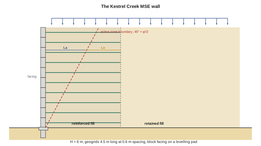
At Kestrel Bay, Ridgeway Road is raised as it approaches the new Kestrel Creek culvert, and the road authority does not want the embankment side slopes to encroach on the creek. The team proposes an MSE wall 6.0 m high along the creek side, with a precast block facing and geogrid reinforcement. Because the wall stands on 4 m of sand over the varved clay, its tolerance of settlement is one of its main advantages.
Components and materials
The reinforcement is either inextensible, such as steel strips and welded wire mesh, or extensible, such as polyester and polyethylene geogrids and geotextiles. The difference matters for design: inextensible reinforcement limits the lateral strain of the backfill, so near the top of the wall the soil is close to the at-rest state, while extensible reinforcement allows enough strain for the active state to develop throughout. The facing is precast concrete panels, dry-stacked modular blocks, welded wire with stone fill, or a wrapped geotextile with a protective cover. It carries little load in most systems; its main job is to hold the soil locally and to give the wall its appearance.
The reinforced fill is a select granular material with few fines, typically limited to about 15 % passing the 75 µm sieve, a friction angle of at least 34° and, for steel reinforcement, controlled chemistry to limit corrosion. The retained fill behind the reinforced zone and the foundation soil can be poorer. The team specifies a crushed granular fill for the reinforced zone, with \(\phi' = 34^\circ\), and assumes \(\phi' = 30^\circ\) for the mixed embankment fill behind it.
MSE walls are proprietary or generic. Proprietary systems, sold by companies that supply the facing and reinforcement, come with design calculations prepared by the supplier's engineer to the owner's requirements. Generic walls are designed by the owner's engineer. In either case, the owner's geotechnical engineer is responsible for external and global stability, and for specifying the foundation, the fill, the drainage and the performance requirements. In Canada, MSE walls for highways are designed under the Canadian Highway Bridge Design Code; for the City of Thunder Bay the team uses the same approach.
External stability
The reinforced block of length \(L\) and height \(H\) is treated as a gravity wall loaded by the active thrust of the retained fill. The checks are the same as for a gravity wall: sliding along the base of the block, on the weaker of the reinforced fill, the foundation soil or the soil-reinforcement interface; the eccentricity of the resultant, limited to \(L/6\) for walls on soil in many specifications; bearing on the foundation; and global stability. The minimum reinforcement length is usually taken as \(0.7H\), and not less than about 2.4 m, even when the calculations would allow less.
The bearing pressure under an MSE wall is calculated by Meyerhof's method, \(q = V/(L - 2e)\), and compared with the bearing resistance. Because the wall is flexible, it can tolerate differential settlements of about 1 in 100 along its length for typical panel joints, and more for modular blocks, far more than a concrete wall. This is the reason MSE walls are often chosen for soft ground, but it does not remove the need for adequate bearing and global stability, which on soft clay frequently governs the reinforcement length.
Internal stability
Inside the reinforced zone, each layer of reinforcement must carry the lateral earth pressure from its tributary height without breaking, and must be anchored far enough beyond the potential failure surface not to pull out. The simplified method, now standard in North American practice, takes the maximum tension in a layer at depth \(z\) as
where \(\sigma_v\) is the vertical stress at the layer, including surcharge, and \(S_v\) is the vertical spacing. For geosynthetics, \(K_r = K_a\) of the reinforced fill. For steel strips and meshes, \(K_r\) is larger near the top, about 1.7\(K_a\) for strips and 2.5\(K_a\) for bar mats at the surface, falling to \(K_a\) at about 6 m depth, to account for the at-rest conditions that inextensible reinforcement maintains.
The failure surface separates an active zone near the facing from a resistant zone behind it. For extensible reinforcement it is the Rankine plane at \(45^\circ + \phi'/2\) from the toe; for inextensible reinforcement it is a bilinear surface reaching \(0.3H\) behind the facing. The embedment length \(L_e\) beyond the surface provides the pullout resistance
where \(F^*\) is the pullout resistance factor, about \(\tfrac23\tan\phi'\) for geogrids in the absence of test data, \(\alpha\) is a scale correction for extensible reinforcement, about 0.8 for geogrids, \(C = 2\) for sheet and grid reinforcement, which have two faces, and \(\sigma'_v\) is the overburden at the layer without traffic surcharge, because traffic may be absent when the layer is loaded. The embedment length should be at least about 1 m.
The long-term strength of a geosynthetic is much less than its short-term tensile strength. Installation damage, creep under sustained load and chemical or biological degradation each reduce it, and the long-term design strength is
with reduction factors that depend on the polymer, the product and the fill, and are established by testing to standard protocols. Creep is usually the largest; for polyester geogrids, \(RF_{CR}\) is about 1.4 to 1.7, and for polyethylene and polypropylene products it is larger. Steel reinforcement has no creep reduction but loses section to corrosion over the design life, for which a sacrificial thickness is allowed.
Worked problem
The Kestrel Creek MSE wall
The wall is 6.0 m high, with geogrid layers 4.5 m long at 0.6 m spacing in reinforced fill with \(\phi' = 34^\circ\) and \(\gamma = 20\) kN/m³. The retained fill has \(\phi' = 30^\circ\) and \(\gamma = 19\) kN/m³, and the traffic surcharge is 12 kPa. The geogrid has \(T_{ult} = 80\) kN/m with reduction factors of 1.15, 1.60 and 1.10. Check external sliding and eccentricity, and the rupture and pullout of the bottom layer, as an illustration of the method with unfactored loads.
Show solution
- External: \(W = 20(6.0)(4.5) = 540\) kN/m; \(K_a = 0.333\) for the retained fill.
- \[F_1 = \tfrac12(0.333)(19)(6.0)^2 = 114.0\ \text{kN/m} \qquad F_2 = 0.333(12)(6.0) = 24.0\ \text{kN/m}\]
- \[\text{Sliding ratio} = \frac{540\tan 30^\circ}{138} = 2.26 \qquad e = \frac{114.0(2.0) + 24.0(3.0)}{540} = 0.56\ \text{m} < L/6 = 0.75\ \text{m}\]
- Internal, bottom layer at \(z = 5.70\) m, with \(K_r = K_a = 0.283\):
- \[T_{max} = 0.283(20 \times 5.70 + 12)(0.6) = 21.4\ \text{kN/m} \qquad T_{al} = \frac{80}{1.15(1.60)(1.10)} = 39.5\ \text{kN/m}\]
- \[L_e = 4.5 - 0.16 = 4.34\ \text{m} \qquad P_r = \tfrac23\tan 34^\circ(0.8)(20 \times 5.70)(2)(4.34) = 356\ \text{kN/m}\]
Answer: The block is stable against sliding with a ratio of about 2.2 and its resultant is within \(L/6\). In the bottom layer, the grid works at about 55 % of its long-term strength, and its pullout resistance is many times the tension. The top layer, with the shortest embedment, governs pullout, with a ratio of about 2.1.
The script runs the same checks for every layer, from the top of the wall to the bottom, and reports the shortest embedment length.
# MSE wall for the Kestrel Creek approach: external stability and internal geogrid design
from math import tan, radians, exp, pi
UNITS = "SI"
SI = UNITS == "SI"
L, F, P = ("m", "kN/m", "kPa") if SI else ("ft", "lb/ft", "psf")
if SI:
    H, Lr, Sv, gr, phr, gf, phf, q = 6.0, 4.5, 0.6, 20.0, 34.0, 19.0, 30.0, 12.0
    Tult, RFid, RFcr, RFd = 80.0, 1.15, 1.60, 1.10        # geogrid ultimate strength (kN/m) and reduction factors
else:
    H, Lr, Sv, gr, phr, gf, phf, q = 20.0, 15.0, 2.0, 125.0, 34.0, 120.0, 30.0, 250.0
    Tult, RFid, RFcr, RFd = 5480.0, 1.15, 1.60, 1.10      # lb/ft
Kaf = tan(radians(45 - phf / 2)) ** 2; Kar = tan(radians(45 - phr / 2)) ** 2
print(f"H = {H:g} {L}, reinforcement length L = {Lr:g} {L} (L/H = {Lr/H:.2f}), vertical spacing {Sv:g} {L}")
# external stability: the reinforced block as a gravity wall, retained fill thrust behind it
W = gr * H * Lr; F1 = 0.5 * Kaf * gf * H * H; F2 = Kaf * q * H
e = (F1 * H / 3 + F2 * H / 2) / W
print(f"Block weight {W:.0f} {F}; thrust {F1:.1f} (soil) + {F2:.1f} (traffic) {F}")
print(f"Sliding on the base (soil-soil, phi' {phf:.0f} deg, the weaker): resistance {W*tan(radians(phf)):.0f} vs {F1+F2:.0f} -> ratio {W*tan(radians(phf))/(F1+F2):.2f}")
print(f"Eccentricity e = {e:.2f} {L}; limit L/6 = {Lr/6:.2f} {L}; Meyerhof pressure {W/(Lr-2*e):.0f} {P} on L' = {Lr-2*e:.2f} {L}")
# internal stability, simplified method for geosynthetics: Kr = Ka of the reinforced fill
Tal = Tult / (RFid * RFcr * RFd)
print(f"\nGeogrid: Tult {Tult:g} {F}, long-term design strength Tal = Tult/(RFid RFcr RFd) = {Tal:.1f} {F}")
Fstar, alpha, C = 2 / 3 * tan(radians(phr)), 0.8, 2
nl = round(H / Sv); worst = 0
print(" layer  depth   Tmax    Tal/Tmax   La      Le    pullout/Tmax")
for i in range(nl):
    z = Sv / 2 + i * Sv                                # layer depth below top of wall
    Tmax = Kar * (gr * z + q) * Sv
    La = (H - z) * tan(radians(45 - phr / 2))           # behind the Rankine plane (active zone)
    Le = Lr - La
    Pr = Fstar * alpha * gr * z * C * Le                # traffic surcharge ignored for pullout
    worst = max(worst, Tmax / Tal)
    if i in (0, 1, nl // 2, nl - 2, nl - 1):
        print(f" {i+1:4d} {z:7.2f} {Tmax:8.1f} {Tal/Tmax:9.2f} {La:7.2f} {Le:7.2f} {Pr/Tmax:9.2f}")
print(f"Highest Tmax/Tal = {worst:.2f}, in the bottom layer: one grid strength at one spacing works over the full height")
print(f"Shortest embedment length beyond the active zone: {Lr - (H - Sv/2)*tan(radians(45 - phr/2)):.2f} {L} at the top layer (minimum used: {1.0 if SI else 3.0} {L})")H = 6 m, reinforcement length L = 4.5 m (L/H = 0.75), vertical spacing 0.6 m
Block weight 540 kN/m; thrust 114.0 (soil) + 24.0 (traffic) kN/m
Sliding on the base (soil-soil, phi' 30 deg, the weaker): resistance 312 vs 138 -> ratio 2.26
Eccentricity e = 0.56 m; limit L/6 = 0.75 m; Meyerhof pressure 159 kPa on L' = 3.39 m
Geogrid: Tult 80 kN/m, long-term design strength Tal = Tult/(RFid RFcr RFd) = 39.5 kN/m
layer depth Tmax Tal/Tmax La Le pullout/Tmax
1 0.30 3.1 12.95 3.03 1.47 2.08
2 0.90 5.1 7.77 2.71 1.79 4.55
6 3.30 13.2 2.99 1.44 3.06 11.00
9 5.10 19.3 2.04 0.48 4.02 15.26
10 5.70 21.4 1.85 0.16 4.34 16.66
Highest Tmax/Tal = 0.54, in the bottom layer: one grid strength at one spacing works over the full height
Shortest embedment length beyond the active zone: 1.47 m at the top layer (minimum used: 1.0 m)Reading the results
The table shows the typical pattern. Tension increases with depth, so the lower layers are the most heavily loaded in rupture, while pullout is critical near the top, where the overburden is small and most of the layer lies inside the active zone. With one grid strength at one spacing, the bottom layer is at a ratio of about 0.55, so a single product works over the full height; on a taller wall the designer would use a stronger grid or a closer spacing in the lower third. The shortest embedment length, at the top layer, is 1.47 m, above the minimum of 1.0 m.
The external checks pass easily. They do not, however, cover the most serious risk at this site: the wall sits 4 m above the varved clay, beside a creek that has cut a bank into it. Global stability, with a slip surface passing beneath the reinforced block and into the clay, must be checked by the methods of lessons 7 and 8, and scour of the creek at the toe must be prevented. Both return in the capstone.
Construction and performance
MSE walls are built in lifts. A concrete or crushed stone levelling pad sets the line and grade of the first course of facing; reinforcement is laid on compacted fill at each level, connected to the facing and pulled taut; the next lift of fill is placed and compacted, with light equipment within about 1 m of the face. Facing alignment is controlled by the batter of the units and the care of the compaction. Typical tolerances are about 20 mm in 3 m of height.
The facing must be embedded to protect the toe: commonly at least \(H/20\) on level ground, more in front of a slope, and below the depth of scour where the wall is beside water. Drainage is placed behind and beneath the reinforced zone, especially where groundwater or infiltration could saturate the retained fill. Where road salt is used, as on Ridgeway Road, the facing joints and the fill near the top need protection from chloride-laden runoff, and steel reinforcement is avoided or given a larger corrosion allowance.
| Reinforcement | Behaviour | Kr near the top | Critical surface | Main durability issue |
|---|---|---|---|---|
| Steel strips | inextensible | 1.7 Ka | bilinear, 0.3H at the top | corrosion |
| Steel bar mats, welded wire | inextensible | 2.5 Ka | bilinear | corrosion |
| Polyester geogrid | extensible | Ka | Rankine plane | creep, hydrolysis |
| Polyethylene or polypropylene geogrid | extensible | Ka | Rankine plane | creep, oxidation |
Practical points
- Use a reinforcement length of at least \(0.7H\), and lengthen it if global stability or bearing requires.
- Check rupture in the lower layers and pullout in the upper layers.
- Use the long-term design strength of geosynthetics, with product-specific reduction factors.
- Specify the reinforced fill, its compaction and the drainage; they control the wall's behaviour.
- Embed the toe below scour depth beside water, and check global stability on soft ground.
Common mistakes
MistakeUsing the ultimate tensile strength of a geogrid in the rupture check.
InsteadUse the long-term design strength after reduction factors.
MistakeIncluding the traffic surcharge in the pullout resistance.
InsteadPullout uses the overburden of the soil only; traffic may be absent.
MistakeTreating steel strips with \(K_r = K_a\) near the top.
InsteadInextensible reinforcement holds the soil near at rest; \(K_r\) is larger near the top.
MistakeAccepting the external checks as proof of overall safety.
InsteadGlobal stability beneath the wall must be checked separately.
Summary and key terms
- MSE walls reinforce the backfill with steel or geosynthetic layers behind a light facing.
- External stability: sliding, eccentricity within \(L/6\), bearing and global stability of the reinforced block.
- Internal stability: \(T_{max} = K_r\sigma_v S_v\) against rupture and \(P_r = F^*\alpha\sigma'_v C L_e\) against pullout.
- Long-term geosynthetic strength: \(T_{al} = T_{ult}/(RF_{ID}RF_{CR}RF_D)\).
- Minimum length \(0.7H\); embedment at least \(H/20\) and below scour.
- The Kestrel Creek wall: 6.0 m high with 4.5 m grids; the bottom layer works at about 55 % of its long-term strength.
- Mechanically stabilized earth wall
- A retaining wall of compacted fill reinforced with horizontal layers of tensile reinforcement behind a facing.
- Geogrid
- A polymer grid used as soil reinforcement.
- Inextensible reinforcement
- Reinforcement, such as steel, whose strain at failure is much less than that of the soil.
- Active zone
- The part of the reinforced fill between the facing and the potential failure surface.
- Embedment length
- The length of reinforcement beyond the potential failure surface that resists pullout.
- Pullout resistance factor
- The coefficient relating the shear resistance on the reinforcement to the overburden stress.
- Reduction factor
- A factor applied to the ultimate strength of a geosynthetic for installation damage, creep or degradation.
- Levelling pad
- The unreinforced concrete or stone strip on which the first course of facing is placed.
Practice problems
Work each problem on paper first, then reveal the answer to check.
A geogrid has \(T_{ult} = \) 60 kN/m with reduction factors 1.2, 1.7 and 1.1. Find its long-term design strength.
Show answer
\(T_{al} = 60/2.24 = 26.7\) kN/m.
Find \(T_{max}\) for a geogrid layer at 4.0 m depth in fill with \(K_a = 0.28\), \(\gamma = 20\) kN/m³, spacing 0.5 m and no surcharge.
Show answer
\(T_{max} = 0.28(80)(0.5) = 11.2\) kN/m.
An MSE wall is 8 m high. What minimum reinforcement length would you start with?
Show answer
\(0.7H = 5.6\) m, then check external and global stability.
Why is pullout usually most critical in the top layers?
Show answer
The overburden is smallest there and most of the layer is inside the active zone, so the embedment length and the normal stress on it are both small.
Lesson quiz · 5 questions
Score 60% or more to complete this lesson.
Create a free account to save your progress, take quizzes and earn a certificate.