
CIV-440 · Lesson 3 of 12 · 22 min
Gravity and cantilever retaining walls
With the pressures in hand, the team can design the Ridgeway Road wall itself. A retaining wall must satisfy two sets of requirements. As a structure, its stem and base must carry the bending and shear the pressures produce, which is the subject of reinforced concrete design. As a geotechnical system, the wall and the soil it sits on must not slide, overturn, fail in bearing or take part in a deeper slip of the whole slope. This lesson deals with the geotechnical checks, which usually set the width of the base.
Types of retaining wall
Gravity walls of mass concrete, masonry, gabions or stacked precast blocks resist the thrust by their own weight. They are economical for low heights, up to about 3 m, and tolerate some settlement if built of flexible units. Cantilever walls of reinforced concrete use a thin stem fixed to a base slab; the soil on the heel adds to the weight that resists overturning and sliding. They are the usual choice for heights of about 3 to 8 m. Counterfort walls add triangular ribs behind the stem for greater heights. Mechanically stabilized earth walls, which reinforce the backfill itself, are the subject of lesson 4, and embedded walls, which rely on passive resistance below an excavation, of lessons 5 and 6.
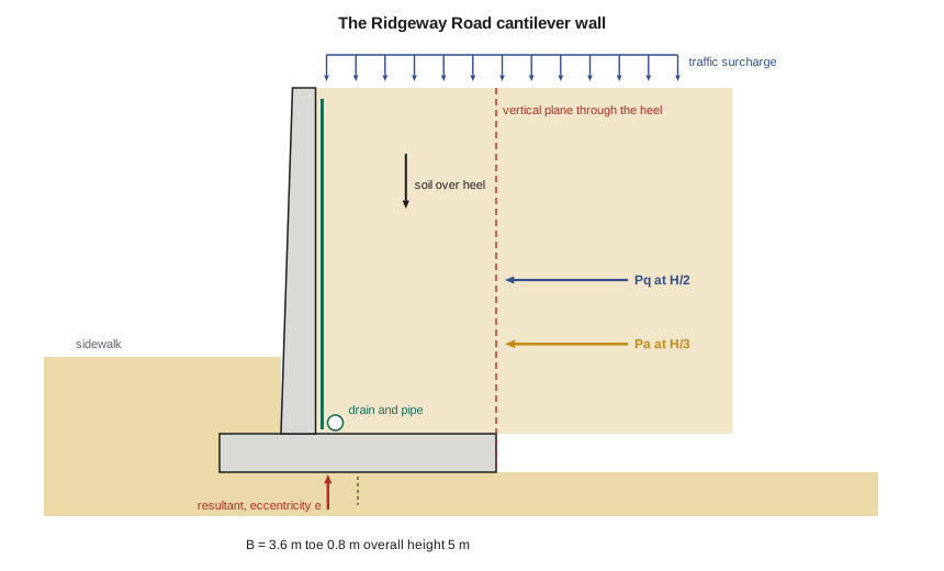
The choice depends on height, the space available, the foundation soil, appearance and cost. On Ridgeway Road, the property line leaves room for a base about 3.5 m wide behind the new sidewalk, the wall is 5.0 m high overall and the foundation is the compact sand. A cast-in-place cantilever wall with a short toe and a long heel fits these constraints.
The stability checks
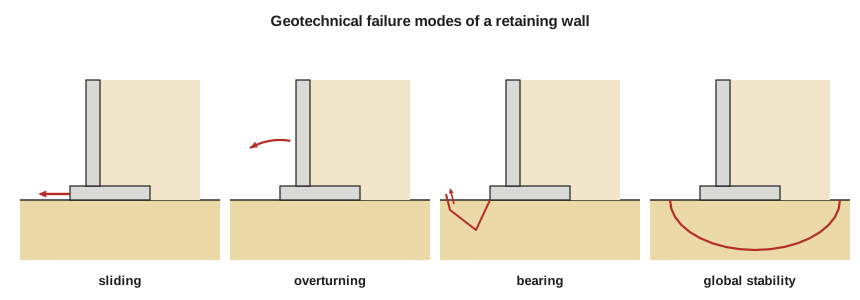
The wall is analysed as a rigid body consisting of the concrete and the soil directly above the heel, loaded by the active thrust on a vertical plane through the heel. Four modes of failure are checked.
Sliding. The horizontal thrust must be resisted by friction on the underside of the base. For concrete cast on granular soil, the friction angle is close to the friction angle of the soil, and the sliding resistance is \(V\tan\delta_b\), where \(V\) is the vertical force on the base. Passive resistance in front of the toe is usually ignored, or only its lower part is counted, because the soil in front may be excavated for utilities, frozen in winter or simply not compacted. A shear key below the base, or a wider base, increases the resistance.
Overturning. The wall tends to rotate about its toe. In allowable stress design, the factor of safety against overturning, the ratio of resisting to overturning moments about the toe, is traditionally at least 2.0. In limit states design, the same requirement is expressed as a limit on the eccentricity of the resultant: it must stay within the middle third or half of the base, depending on the code and the foundation material. A resultant in the middle third keeps the whole base in compression.
Bearing. The base pressure must be well below the bearing capacity of the foundation soil. Because the resultant is eccentric and inclined, the bearing capacity is calculated on Meyerhof's effective width \(B' = B - 2e\), with inclination factors that reduce it considerably. For a wall, the inclination factors are the most important correction in the bearing capacity equation, because the horizontal load is a large fraction of the vertical.
Global stability. The wall, its backfill and the ground beneath can fail together along a deep slip surface passing beneath the base, especially where the wall sits on a slope or above weak soil. This is checked by the slope stability methods of lessons 7 and 8, and for walls over soft clay it often governs.
Allowable stress and limit states design
In Canada, walls are designed by limit states design. Road retaining walls follow the Canadian Highway Bridge Design Code; other walls follow the National Building Code with the Canadian Foundation Engineering Manual. The earth pressure is multiplied by a load factor (1.25 in this design, with 1.7 on the traffic surcharge), the dead load by 0.9 where it resists and by 1.1 where it adds to the bearing pressure, and the sliding and bearing resistances by geotechnical resistance factors of 0.8 and 0.5, which are typical values in Canadian practice. The serviceability limit state is checked with unfactored loads: the resultant should stay in the middle third of the base under service loads, and the wall must not tilt or settle excessively.
Worked problem
Stability of the Ridgeway Road wall
The wall is 5.0 m high overall, with a 0.5 m base slab, a stem 0.30 m thick at the top and 0.45 m at the base, and a 0.8 m toe. The first trial base width is 3.2 m. Concrete weighs 23.5 kN/m³; the backfill has \(\phi' = 32^\circ\) and \(\gamma = 20\) kN/m³; the foundation sand has \(\phi' = 34^\circ\), with the water table 1.0 m below the base, which is 1.5 m below the finished grade in front of the wall. Check sliding and bearing by limit states design.
Show solution
- Vertical forces: base 37.6, stem 31.7 + 7.9, soil over the heel 175.5, total \(V = 252.8\) kN/m, with a moment about the toe of 492.7 kN·m/m.
- Thrusts: \(P_a = 76.8\) kN/m at 1.67 m and \(P_q = 18.4\) kN/m at 2.50 m.
- \[H_f = 1.25(76.8) + 1.7(18.4) = 127.4\ \text{kN/m} \qquad V_f = 0.9(252.8) = 227.5\ \text{kN/m}\]
- \[\phi R_s = 0.8\,V_f\tan 34^\circ = 0.8(227.5)(0.675) = 122.8\ \text{kN/m} < 127.4\]
- Sliding fails, by 4 %. Widening the base to 3.6 m adds 0.4 m of heel and soil above it:
- \[V = 293.5\ \text{kN/m} \qquad \phi R_s = 0.8(0.9)(293.5)\tan 34^\circ = 142.5\ \text{kN/m} > 127.4\]
- Bearing, with the factored eccentricity of 0.552 m and the load inclination of 25.7°: \(B' = 2.50\) m, \(q_u = 445\) kPa, and \(0.5\,q_u B' = 555\) kN/m against \(V_f = 264\) kN/m.
Answer: The 3.2 m base fails in sliding; a 3.6 m base passes with a utilization of 0.89. Bearing is not critical, at a utilization of about 0.5 even with the strong inclination reduction.
Sofia's script sets out the weights and moments, finds the resultant and its eccentricity, and then makes the sliding and bearing checks with the inclination factors.
# Stability of the cantilever retaining wall on Ridgeway Road
from math import tan, radians, exp, pi, atan, degrees
UNITS = "SI"
SI = UNITS == "SI"
L, F, P, MU = ("m", "kN/m", "kPa", "kN.m/m") if SI else ("ft", "lb/ft", "psf", "lb.ft/ft")
if SI:
    H, B, toe, t, st_top, st_bot = 5.0, 3.2, 0.8, 0.5, 0.30, 0.45      # overall height, base width, toe, base thickness, stem
    gc, gb, phi_b, q, gw = 23.5, 20.0, 32.0, 12.0, 9.81
    gs, gs_sub, phi_f, Df, zw = 18.0, 9.99, 34.0, 1.5, 1.0            # foundation sand, depth of base, water below base
else:
    H, B, toe, t, st_top, st_bot = 16.0, 10.5, 2.5, 1.5, 1.0, 1.5
    gc, gb, phi_b, q, gw = 150.0, 125.0, 32.0, 250.0, 62.4
    gs, gs_sub, phi_f, Df, zw = 115.0, 63.6, 34.0, 5.0, 3.0
hs = H - t; heel = B - toe - st_bot
Ka = tan(radians(45 - phi_b / 2)) ** 2
# vertical forces and their lever arms about the toe
parts = [("base", B * t * gc, B / 2),
         ("stem (rectangle)", st_top * hs * gc, toe + st_bot - st_top / 2),
         ("stem (taper)", 0.5 * (st_bot - st_top) * hs * gc, toe + (st_bot - st_top) * 2 / 3),
         ("soil over heel", heel * hs * gb, B - heel / 2)]
V = sum(w for _, w, _ in parts); MR = sum(w * x for _, w, x in parts)
for n, w, x in parts: print(f"{n:17s} W = {w:7.1f} {F}  arm {x:5.2f} {L}")
Pa, Pq = 0.5 * Ka * gb * H * H, Ka * q * H          # Rankine on the vertical plane through the heel
MO = Pa * H / 3 + Pq * H / 2
print(f"Sum V = {V:.1f} {F}; resisting moment {MR:.1f} {MU}")
print(f"Active thrust {Pa:.1f} + surcharge {Pq:.1f} = {Pa + Pq:.1f} {F}; overturning moment {MO:.1f} {MU}")
x = (MR - MO) / V; e = B / 2 - x
print(f"Resultant at {x:.2f} {L} from the toe, eccentricity e = {e:.3f} {L} (B/6 = {B/6:.3f}, B/4 = {B/4:.3f})")
qmax, qmin = V / B * (1 + 6 * e / B), V / B * (1 - 6 * e / B)
print(f"Contact pressure (trapezoid): {qmax:.0f} to {qmin:.0f} {P}")

def bearing(Vv, Hh, Bp):        # Meyerhof effective width, strip, with load inclination factors, water at zw below base
    f = radians(phi_f); Nq = exp(pi * tan(f)) * tan(radians(45 + phi_f / 2)) ** 2; Ng = 2 * (Nq + 1) * tan(f)
    th = degrees(atan(Hh / Vv)); iq = (1 - th / 90) ** 2; ig = (1 - th / phi_f) ** 2
    geff = gs_sub + (gs - gs_sub) * min(zw / Bp, 1.0)
    return Df * gs * Nq * iq + 0.5 * geff * Bp * Ng * ig, th, iq, ig
def statics(B):
    heel = B - toe - st_bot
    parts = [B * t * gc * B / 2, st_top * hs * gc * (toe + st_bot - st_top / 2),
             0.5 * (st_bot - st_top) * hs * gc * (toe + (st_bot - st_top) * 2 / 3), heel * hs * gb * (B - heel / 2)]
    V = B * t * gc + st_top * hs * gc + 0.5 * (st_bot - st_top) * hs * gc + heel * hs * gb
    return V, sum(parts)
if SI:
  for B in (3.2, 3.6):
    V, MR = statics(B)
    print(f"\n--- Base width B = {B} m: V = {V:.1f} kN/m, resisting moment {MR:.1f} kN.m/m")
    # limit states: earth pressure x1.25, surcharge x1.7, dead load x0.9 (resisting) or x1.1; resistance factors 0.8 sliding, 0.5 bearing
    Hf = 1.25 * Pa + 1.7 * Pq
    for case, fD in (("dead load minimum (sliding)", 0.9), ("dead load maximum (bearing)", 1.1)):
        Vf = fD * V; MOf = 1.25 * Pa * H / 3 + 1.7 * Pq * H / 2
        ef = B / 2 - (fD * MR - MOf) / Vf; Bp = B - 2 * ef
        Rs = 0.8 * Vf * tan(radians(phi_f))
        qu, th, iq, ig = bearing(Vf, Hf, Bp)
        print(f"ULS, {case}: Vf = {Vf:.1f}, Hf = {Hf:.1f} {F}, e = {ef:.3f} m, B' = {Bp:.2f} m, load inclination {th:.1f} deg")
        print(f"  sliding: 0.8 Vf tan(phi) = {Rs:.1f} vs Hf {Hf:.1f} -> utilization {Hf / Rs:.2f}")
        print(f"  bearing: qu = {qu:.0f} kPa (iq {iq:.2f}, i_gamma {ig:.2f}); 0.5 qu B' = {0.5*qu*Bp:.0f} vs Vf {Vf:.0f} kN/m -> utilization {Vf/(0.5*qu*Bp):.2f}")
else:
    Hh = Pa + Pq; Bp = B - 2 * e
    FSs = V * tan(radians(phi_f)) / Hh; FSo = MR / MO
    qu, th, iq, ig = bearing(V, Hh, Bp)
    print(f"\nASD: sliding FS = V tan(phi)/H = {FSs:.2f} (need 1.5); overturning FS = {FSo:.2f} (need 2.0)")
    print(f"  bearing: B' = {Bp:.2f} ft, inclination {th:.1f} deg, qu = {qu:.0f} psf; q on B' = {V/Bp:.0f} psf; FS = {qu/(V/Bp):.2f} (need 3.0)")
print(f" LRFD comparison: phi_tau = 1.0 gives {V*0.9*tan(radians(phi_f)):.0f} vs 1.5 x {Pa:.0f} + 1.75 x {Pq:.0f} = {1.5*Pa+1.75*Pq:.0f} lb/ft")base W = 37.6 kN/m arm 1.60 m stem (rectangle) W = 31.7 kN/m arm 1.10 m stem (taper) W = 7.9 kN/m arm 0.90 m soil over heel W = 175.5 kN/m arm 2.23 m Sum V = 252.8 kN/m; resisting moment 492.7 kN.m/m Active thrust 76.8 + surcharge 18.4 = 95.3 kN/m; overturning moment 174.1 kN.m/m Resultant at 1.26 m from the toe, eccentricity e = 0.340 m (B/6 = 0.533, B/4 = 0.800) Contact pressure (trapezoid): 129 to 29 kPa --- Base width B = 3.2 m: V = 252.8 kN/m, resisting moment 492.7 kN.m/m ULS, dead load minimum (sliding): Vf = 227.5, Hf = 127.4 kN/m, e = 0.699 m, B' = 1.80 m, load inclination 29.2 deg sliding: 0.8 Vf tan(phi) = 122.8 vs Hf 127.4 -> utilization 1.04 bearing: qu = 373 kPa (iq 0.46, i_gamma 0.02); 0.5 qu B' = 336 vs Vf 227 kN/m -> utilization 0.68 ULS, dead load maximum (bearing): Vf = 278.0, Hf = 127.4 kN/m, e = 0.508 m, B' = 2.18 m, load inclination 24.6 deg sliding: 0.8 Vf tan(phi) = 150.0 vs Hf 127.4 -> utilization 0.85 bearing: qu = 466 kPa (iq 0.53, i_gamma 0.08); 0.5 qu B' = 509 vs Vf 278 kN/m -> utilization 0.55 --- Base width B = 3.6 m: V = 293.5 kN/m, resisting moment 631.1 kN.m/m ULS, dead load minimum (sliding): Vf = 264.1, Hf = 127.4 kN/m, e = 0.552 m, B' = 2.50 m, load inclination 25.7 deg sliding: 0.8 Vf tan(phi) = 142.5 vs Hf 127.4 -> utilization 0.89 bearing: qu = 445 kPa (iq 0.51, i_gamma 0.06); 0.5 qu B' = 555 vs Vf 264 kN/m -> utilization 0.48 ULS, dead load maximum (bearing): Vf = 322.8, Hf = 127.4 kN/m, e = 0.388 m, B' = 2.82 m, load inclination 21.5 deg sliding: 0.8 Vf tan(phi) = 174.2 vs Hf 127.4 -> utilization 0.73 bearing: qu = 560 kPa (iq 0.58, i_gamma 0.13); 0.5 qu B' = 791 vs Vf 323 kN/m -> utilization 0.41
Reading the results
The trial wall with a 3.2 m base has its service resultant 0.340 m from the centre, well inside the middle third (0.533 m), and a contact pressure ranging from 129 kPa at the toe to 29 kPa at the heel. It looks comfortable, yet it fails the factored sliding check, because sliding is the mode where the load factor on the earth pressure and the reduced dead load act together. The extra 0.4 m of heel adds soil weight cheaply, and the 3.6 m wall passes with a margin of about 11 %. A shear key was considered and rejected: it would have to be cut into the sand below the water table at the toe, where the bottom of the excavation is already close to the water.
Bearing is rarely critical for walls on compact sand, but the inclination reduction is a reminder that a wall's base is not an ordinary footing. A footing carrying the same vertical load with no horizontal load would have several times the bearing capacity.
Drainage, frost and construction
The geotechnical design of a wall goes beyond the stability checks. The base must be founded below the depth of frost penetration, or on non-frost-susceptible material that extends below it; lesson 11 shows how deep frost reaches under a cleared road. The front of the base needs a minimum cover for frost and erosion. The drainage described in lesson 2 must be detailed and its outlets protected. The backfill must be specified, placed in thin layers and compacted with light equipment near the stem. Expansion and contraction joints are needed at intervals of about 9 m along the wall, with the drainage continuous across them.
Settlement and tilt matter for the appearance of the wall and for the sidewalk and railing on top. A wall on compact sand settles a few millimetres, mostly during construction. A wall over soft clay can tilt outward as the clay consolidates under the higher toe pressure, and is often built with a small backward batter to allow for it.
| Check | Limit states (3.6 m base) | Comment |
|---|---|---|
| Sliding | utilization 0.89 | governs the base width |
| Overturning / eccentricity | e = 0.552 m factored, within B/4 | comfortable |
| Bearing | utilization 0.48 | inclination factors important |
| Global stability | checked by slip circles | the sand is strong; satisfactory |
| Frost | base below frost depth | lesson 11 |
Practical points
- Treat the concrete and the soil over the heel as one rigid body loaded on a vertical plane through the heel.
- Check sliding first; it usually governs, and a longer heel is the cheapest cure.
- Use Meyerhof's effective width and inclination factors for bearing.
- Ignore passive resistance at the toe unless it is certain to remain.
- Check global stability whenever the wall sits on or near a slope, or above weak soil.
Common mistakes
MistakeChecking bearing with the average pressure \(V/B\) and no inclination factors.
InsteadUse \(B' = B - 2e\) and the inclination factors; they can halve the capacity.
MistakeCounting the full passive resistance in front of the toe.
InsteadThe soil may be removed or frozen; ignore it or count only a reduced lower part.
MistakeUsing the same load factor on dead load in every check.
InsteadUse the minimum factor where dead load resists and the maximum where it adds to bearing pressure.
MistakeJudging the wall safe because the resultant is in the middle third.
InsteadThe eccentricity check does not cover sliding, bearing or global stability.
Summary and key terms
- Retaining walls are checked for sliding, overturning (eccentricity), bearing and global stability.
- The cantilever wall is analysed as a rigid body including the soil on the heel, with the thrust on a vertical plane through the heel.
- Sliding resistance is \(V\tan\delta_b\); passive resistance at the toe is usually ignored.
- Bearing uses the effective width and inclination factors.
- In limit states design, sliding of the 3.2 m trial base failed by 4 %; a 3.6 m base gives a utilization of 0.89.
- Founding depth, drainage, joints and compaction are part of the geotechnical design.
- Cantilever retaining wall
- A reinforced concrete wall with a stem fixed to a base slab, using the weight of soil on the heel for stability.
- Gravity wall
- A wall that resists earth pressure by its own weight.
- Toe
- The part of the base in front of the stem.
- Heel
- The part of the base behind the stem, beneath the retained soil.
- Shear key
- A downward projection of the base that increases resistance to sliding.
- Eccentricity
- The distance from the centre of the base to the point where the resultant force crosses it.
- Middle third
- The central third of the base; a resultant within it keeps the whole base in compression.
- Global stability
- The stability of the wall together with the surrounding ground against a deep slip surface.
Practice problems
Work each problem on paper first, then reveal the answer to check.
A wall has \(V = 300\) kN/m and a horizontal thrust of 110 kN/m on a base on sand with \(\phi' = 32^\circ\). Find the factor of safety against sliding.
Show answer
\(FS = 300(0.625)/110 = 1.70\).
A 3.0 m base carries \(V = 250\) kN/m with a resultant 1.2 m from the toe. Find the eccentricity and the toe and heel pressures.
Show answer
\(e = 0.30\) m; \(q = 83.3(1 \pm 0.60) = 133\) and 33 kPa.
Why does adding length to the heel improve sliding resistance more cheaply than thickening the base?
Show answer
It adds the weight of the soil above the heel, which costs only excavation and backfill, and moves the resultant back toward the centre.
Under what conditions does global stability usually govern the design of a retaining wall?
Show answer
When the wall sits on a slope, at the crest of a slope, or above soft clay.
Lesson quiz · 5 questions
Score 60% or more to complete this lesson.
Create a free account to save your progress, take quizzes and earn a certificate.