
CIV-440 · Lesson 2 of 12 · 21 min
Earth pressure from surcharge, water, compaction and earthquakes
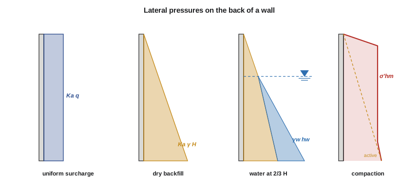
The pressures of lesson 1 are those of a dry, uniform backfill with a level surface and nothing on it. Real walls carry more. Traffic and stockpiles load the surface behind them, water collects in the backfill when drains fail, compaction equipment locks in horizontal stress during construction, and earthquakes add an inertial thrust. Each of these can be larger than the static active pressure, and most retaining wall failures are traced to one of them, above all to water. This lesson adds them to the Ridgeway Road wall.
Uniform and strip surcharges
A uniform surcharge \(q\) over the whole backfill surface adds \(q\) to the vertical effective stress at every depth, so it adds a constant lateral pressure \(K q\) over the full height of the wall. For a wall in the active state, the extra thrust is \(K_a qH\), acting at mid-height. Traffic loading behind road walls is usually represented this way, by an equivalent height of soil. The Canadian Highway Bridge Design Code give live load surcharges that depend on the wall height and the distance of traffic from the wall, roughly equivalent to 0.6 to 1.5 m (2 to 5 ft) of soil. For the Ridgeway Road wall, the team uses 12 kPa, about 0.6 m of fill, with its own load factor in the ultimate limit state checks.
Loads of limited extent, such as a footing, a crane outrigger or a stockpile strip, are treated with elastic solutions modified for the presence of the wall. For a line load \(Q\) per unit length parallel to a rigid wall, the classical result, based on Boussinesq's solution and confirmed by Terzaghi's model tests, is roughly double the elastic stress in a semi-infinite mass, because the wall acts as a mirror. For a strip load \(q\) between angles \(\beta\) and \(\alpha\) measured from the top of the wall, the lateral pressure at depth \(z\) is
with the angles in radians, \(\beta\) being the angle subtended by the strip and \(\alpha\) the angle to its centre line. These elastic pressures apply to walls that do not yield; for yielding walls they are conservative. A simpler method, adequate for many cases, spreads the load at 45° or along the active failure plane and applies the active coefficient to the portion that falls on the wall.
Water: the most common cause of failure
Below the water table, the lateral earth pressure is calculated from the effective stress, and the full water pressure is added. Because \(K_a\) is about 0.3 and the coefficient for water is 1, water roughly triples the lateral pressure at a given depth compared with the effective stress of soil of the same depth. A wall designed for drained backfill that fills with water can be overloaded by 50 % or more, and many failures of small walls happen in the spring, when snowmelt and frozen drain outlets fill the backfill.
Two strategies are used. A drained wall has a free-draining backfill or a geocomposite drain behind it, a perforated collector pipe at its base and outlets that discharge water away from the wall, together with weep holes in the stem. It is designed for no water, or for a small allowance. An undrained wall, such as the wall of a pump station or a basement below the water table, is designed for full hydrostatic pressure from the start, and for uplift on its base. The design report must say which it is, and the maintenance manual must keep the drains working. In a cold climate, frozen outlets are a particular risk; lesson 11 returns to them.
Seepage changes the pressure as well. Where water flows down through the backfill to a drain at the back of the wall, the downward seepage force increases the effective stress, the pore pressure on the wall is smaller than hydrostatic and the drain carries the water away. An inclined or vertical chimney drain against the back of the stem is the most effective arrangement, because it cuts off the flow before it reaches the wall.
Compaction-induced pressure
Backfill is compacted in layers with rollers or plate compactors. Each pass pushes the soil sideways against the wall, and when the roller moves on, much of the horizontal stress remains locked in. Measurements on instrumented walls show that the residual horizontal pressure near the top of the backfill can be several times the active pressure. Ingold's method, widely used in practice, treats the roller as a line load \(p\) per unit width and gives a maximum residual pressure
which is reached at a critical depth \(z_c = K_a\sqrt{2p/(\pi\gamma)}\). Below that depth, the pressure stays at \(\sigma'_{hm}\) down to the depth \(h_c = \sqrt{2p/(\pi\gamma)}/K_a\), where the active pressure catches up, and follows the active line below. The envelope applies to walls that yield little during construction. Heavy vibratory rollers should therefore be kept a short distance from the wall, typically about a metre, with lighter plate compactors used next to it, and the specification should say so.
Earthquake loading
During an earthquake, the backfill accelerates back and forth, and its inertia adds to the thrust on the wall. The Mononobe-Okabe method, developed in Japan in the 1920s after the Kanto earthquake, extends Coulomb's wedge by adding horizontal and vertical inertial forces \(k_h W\) and \(k_v W\). The result is a seismic active coefficient \(K_{AE}\), which, for a vertical wall with level backfill and no vertical acceleration, is
The total seismic thrust is \(P_{AE} = \tfrac12 K_{AE}\gamma H^2\). The dynamic increment, \(P_{AE} - P_a\), is often placed at about 0.6\(H\) above the base rather than at \(H/3\). Seed and Whitman proposed the simple approximation \(\Delta K_{AE} \approx \tfrac34 k_h\). The horizontal seismic coefficient is usually taken as a fraction, often a half, of the peak ground acceleration expressed in units of \(g\), for walls that can move a few centimetres, following the displacement-based reasoning of Richards and Elms.
Seismic design of walls matters most in the active zones of western Canada and the western United States. Thunder Bay lies in a region of low seismicity, where the design ground motions are small. The team nevertheless checks a small coefficient, \(k_h = 0.05\), to show that the effect is minor and that the static load combinations govern.
Worked problem
Additional thrusts on the Ridgeway Road wall
For the 5.0 m wall with granular backfill (\(\phi' = 32^\circ\), \(\gamma = 20\) kN/m³), find the thrust from a traffic surcharge of 12 kPa, the total thrust if the drains block and water rises to two thirds of the height, and the residual compaction pressure from a roller with an equivalent line load of 60 kN/m.
Show solution
- Surcharge, with \(K_a = 0.307\):
- \[P_q = K_a qH = 0.307(12)(5.0) = 18.4\ \text{kN/m at } 2.5\ \text{m}\]
- Water at 3.33 m above the base: the soil thrust uses the buoyant unit weight below the water level, and the water thrust is added:
- \[P = 60.1 + \tfrac12(9.81)(3.33)^2 = 60.1 + 54.5 = 114.6\ \text{kN/m}\]
- Compaction (Ingold):
- \[\sigma'_{hm} = \sqrt{2(60)(20)/\pi} = 27.6\ \text{kPa}\]
Answer: The traffic surcharge adds about a quarter to the active thrust. Blocked drains add half: the thrust rises from 76.8 to 114.6 kN/m. The compaction pressure is nearly constant over the height of the wall and close to the active pressure at its base, so near the top it is several times the active value.
The script repeats these calculations and adds the Mononobe-Okabe coefficient for a range of seismic coefficients.
# Additional pressures on the Ridgeway Road wall: traffic surcharge, water, compaction and earthquake
from math import sin, cos, tan, radians, sqrt, atan, pi
UNITS = "SI"
SI = UNITS == "SI"
L, F, P = ("m", "kN/m", "kPa") if SI else ("ft", "lb/ft", "psf")
H, gam, phi, gw = (5.0, 20.0, 32.0, 9.81) if SI else (16.0, 125.0, 32.0, 62.4)
q = 12.0 if SI else 250.0                   # traffic surcharge used for the wall (about 0.6 m | 2 ft of soil)
Ka = tan(radians(45 - phi / 2)) ** 2
Pa = 0.5 * Ka * gam * H * H; Pq = Ka * q * H
print(f"Static active thrust {Pa:.1f} {F} at {H/3:.2f} {L}; traffic surcharge adds {Pq:.1f} {F} at {H/2:.2f} {L}")
M0 = Pa * H / 3 + Pq * H / 2
print(f"  total {Pa + Pq:.1f} {F}, moment about the base {M0:.1f} {F}.{L}".replace(f"{F}.{L}", "kN.m/m" if SI else "lb.ft/ft"))

# Drains blocked: water rises to 2/3 of the wall height
hw = 2 / 3 * H; gsat = gam                      # use the same unit weight saturated, for simplicity
gb = gsat - gw
Pa_dry = 0.5 * Ka * gam * (H - hw) ** 2 + Ka * gam * (H - hw) * hw + 0.5 * Ka * gb * hw ** 2
Pw = 0.5 * gw * hw ** 2
print(f"\nWater at {hw:.2f} {L} above the base: soil thrust {Pa_dry:.1f} + water {Pw:.1f} = {Pa_dry + Pw:.1f} {F}")
print(f"  that is {(Pa_dry + Pw) / Pa:.2f} times the drained active thrust")

# Compaction-induced pressure (Ingold's method) for a vibratory roller
p_line = 60.0 if SI else 4100.0                 # equivalent line load of the roller, kN/m | lb/ft
sig_hm = sqrt(2 * p_line * gam / pi)
zc = Ka * sqrt(2 * p_line / (pi * gam)); hc = sqrt(2 * p_line / (pi * gam)) / Ka
print(f"\nCompaction (Ingold), roller line load {p_line:g} {F}: residual horizontal pressure {sig_hm:.1f} {P}")
print(f"  constant from z = {zc:.2f} {L} down to z = {hc:.2f} {L}, below which the active pressure governs")

# Mononobe-Okabe seismic active coefficient
def kae(phi, delta, kh, kv=0.0, beta=0.0, alpha=0.0):
    th = atan(kh / (1 - kv)); f, d, b, a = (radians(x) for x in (phi, delta, beta, alpha))
    num = cos(f - th - a) ** 2
    den = cos(th) * cos(a) ** 2 * cos(d + a + th) * (1 + sqrt(sin(f + d) * sin(f - th - b) / (cos(d + a + th) * cos(b - a)))) ** 2
    return num / den
delta = 2 / 3 * phi
for kh in (0.0, 0.05, 0.10, 0.20):
    K = kae(phi, delta, kh)
print(f"kh = {kh:.2f}: KAE = {K:.3f}" + ("" if kh == 0 else f", dynamic increment {0.5*(K - kae(phi, delta, 0))*gam*H*H:.1f} {F} (Seed-Whitman approx. {0.5*0.75*kh*gam*H*H:.1f})"))Static active thrust 76.8 kN/m at 1.67 m; traffic surcharge adds 18.4 kN/m at 2.50 m total 95.3 kN/m, moment about the base 174.1 kN.m/m Water at 3.33 m above the base: soil thrust 60.1 + water 54.5 = 114.6 kN/m that is 1.49 times the drained active thrust Compaction (Ingold), roller line load 60 kN/m: residual horizontal pressure 27.6 kPa constant from z = 0.42 m down to z = 4.50 m, below which the active pressure governs kh = 0.00: KAE = 0.275 kh = 0.05: KAE = 0.306, dynamic increment 7.7 kN/m (Seed-Whitman approx. 9.4) kh = 0.10: KAE = 0.341, dynamic increment 16.4 kN/m (Seed-Whitman approx. 18.8) kh = 0.20: KAE = 0.425, dynamic increment 37.4 kN/m (Seed-Whitman approx. 37.5)
Reading the results
With \(k_h = 0.05\), the seismic coefficient rises from the static Coulomb value of 0.275 to 0.306, and the dynamic increment is 7.7 kN/m, less than half of the traffic surcharge. Because earthquake load combinations use load factors of about 1.0 and do not combine the full traffic load, they do not govern this wall. At \(k_h = 0.2\), which would be typical of a much more active region, the increment would be 37 kN/m and would need careful attention. The Seed and Whitman approximation is close to the full calculation at the larger coefficients.
The water case is the one the team takes most seriously. The wall is designed as a drained wall, with a geocomposite drain against the stem, a perforated pipe at the heel, weep holes at 3 m spacing and outlets protected from freezing. The serviceability check is made for drained conditions, but the ultimate limit state is also checked for water at one third of the height, to give a margin for partial blockage.
| Effect | Pressure shape | Thrust on the 5.0 m wall | Treatment |
|---|---|---|---|
| Active backfill | triangle | 76.8 kN/m | always |
| Traffic surcharge | rectangle | 18.4 kN/m | with live load factor |
| Water to 2/3 H | triangle plus soil | +37.8 kN/m | prevent by drainage |
| Compaction | constant near the top | locked in | limit roller size near the wall |
| Earthquake, kh = 0.05 | increment at about 0.6H | 7.7 kN/m | checked, does not govern |
Sloping and layered backfill
Where the backfill slopes upward behind the wall, the active coefficient increases, because the wedge carries more soil. For a slope at \(\beta\), Rankine's coefficient on a vertical plane becomes
with the thrust acting parallel to the slope. As \(\beta\) approaches \(\phi'\), the coefficient approaches \(\cos\beta\), and the slope behind the wall is itself at the point of failure. For a broken backslope, which rises for some distance and then levels off, the trial wedge method is the most reliable approach. Where the backfill is layered, the pressure in each layer is calculated with its own coefficient applied to the vertical effective stress at that depth, which gives a jump in the pressure diagram at each boundary.
Practical points
- Add surcharges, water and compaction to the active pressure explicitly; list each in the design basis.
- Design walls to be drained, specify the drainage and its outlets, and check what happens if it fails.
- Keep heavy rollers away from the wall and specify light compaction close to it.
- Check seismic loading with the code's ground motions; in low-seismicity regions it rarely governs.
- Use the trial wedge method for irregular backslopes and concentrated loads.
Common mistakes
MistakeAssuming a drained wall will stay drained without maintenance.
InsteadDrains clog and outlets freeze; design for some water and specify maintenance.
MistakeAdding the surcharge as a triangle.
InsteadA uniform surcharge gives a rectangle of pressure \(K_a q\) over the full height.
MistakePlacing the seismic increment at \(H/3\) with the static thrust.
InsteadThe dynamic increment acts higher, at about 0.6\(H\).
MistakeIgnoring compaction pressure on a non-yielding wall such as a culvert.
InsteadRigid walls retain the locked-in compaction stress.
Summary and key terms
- A uniform surcharge \(q\) adds \(K_a q\) over the full height; strip and line loads use elastic solutions.
- Water adds the full hydrostatic pressure; blocked drains can increase the thrust by 50 % or more.
- Ingold: compaction leaves \(\sigma'_{hm} = \sqrt{2p\gamma/\pi}\) near the top of the backfill.
- Mononobe-Okabe: \(K_{AE}\) from Coulomb's wedge with inertial forces; increment at about 0.6\(H\).
- Sloping backfill increases \(K_a\); layered backfill gives jumps in the pressure diagram.
- For the Ridgeway Road wall, traffic adds 18.4, blocked drains 37.8 and \(k_h = 0.05\) only 7.7 kN/m.
- Surcharge
- A load applied to the ground surface behind a wall, such as traffic or a stockpile.
- Equivalent height of soil
- The height of backfill whose weight equals a surcharge, used to represent traffic loading.
- Drained wall
- A wall with drainage that prevents water pressure from building up behind it.
- Weep hole
- An opening through a wall stem that lets water out of the backfill.
- Compaction-induced pressure
- Horizontal stress locked into backfill by compaction equipment.
- Mononobe-Okabe method
- An extension of Coulomb's wedge that includes inertial forces from earthquake shaking.
- Horizontal seismic coefficient
- The horizontal inertial force on the wedge as a fraction of its weight.
- Chimney drain
- A vertical or inclined drainage layer behind a wall that intercepts seepage before it reaches the wall.
Practice problems
Work each problem on paper first, then reveal the answer to check.
A 4.0 m wall with \(K_a = 0.30\) carries a uniform surcharge of 15 kPa. Find the surcharge thrust and its point of action.
Show answer
\(P_q = 0.30(15)(4.0) = 18\) kN/m at 2.0 m.
For the same wall, water rises to the full height. By how much does the water alone add to the thrust?
Show answer
\(\tfrac12(9.81)(4.0)^2 = 78.5\) kN/m, less the reduction in soil thrust from the buoyant unit weight.
Using Seed and Whitman's approximation, estimate the dynamic increment for \(k_h = 0.15\) on a 6 m wall with \(\gamma = 20\) kN/m³.
Show answer
\(\Delta P = \tfrac12(0.75)(0.15)(20)(36) = 40.5\) kN/m, at about 0.6\(H\).
Why should vibratory rollers be kept away from a rigid box culvert during backfilling?
Show answer
The culvert cannot yield, so the large horizontal stress locked in by compaction acts on it permanently.
Lesson quiz · 5 questions
Score 60% or more to complete this lesson.
Create a free account to save your progress, take quizzes and earn a certificate.