
CIV-330 · Lesson 3 of 12 · 23 min
Flexure in singly reinforced beams
Bending is the action that decides the size of most beams and slabs, so flexure is where reinforced concrete design starts. This lesson follows a rectangular beam with tension steel only from first loading to failure, states the assumptions of flexural theory, derives the resistance of a section, sets the limits that keep the failure ductile, and then designs the office floor beam of the operations centre.
Three stages of behaviour
Imagine loading a simply supported beam slowly until it fails. At first the whole section is uncracked; concrete carries both tension and compression, the steel contributes a little through its transformed area, and the beam behaves elastically with the gross moment of inertia. When the stress at the bottom fibre reaches the modulus of rupture, at the cracking moment \(M_{cr} = f_r I_g / y_t\), flexural cracks open and the tension the concrete was carrying jumps to the steel. The stiffness drops sharply.
In the second stage the beam is cracked but both materials are still elastic. The neutral axis moves up, the concrete below it is ignored, and the section is analysed with the cracked transformed moment of inertia. Service loads usually put a beam in this stage, which is why deflection and crack width calculations in lesson 5 use a cracked section.
In the third stage the steel yields. A well-designed beam then keeps rotating at almost constant moment while the cracks widen and the neutral axis rises, until the concrete at the top crushes. The large rotation between first yield and crushing is ductility: it gives visible warning and allows moments to redistribute in continuous members. The design aim is to make sure this sequence happens, with the steel yielding well before the concrete crushes.
Assumptions of flexural theory
Strength calculations for flexure and axial load in A23.3 rest on a short list of assumptions:
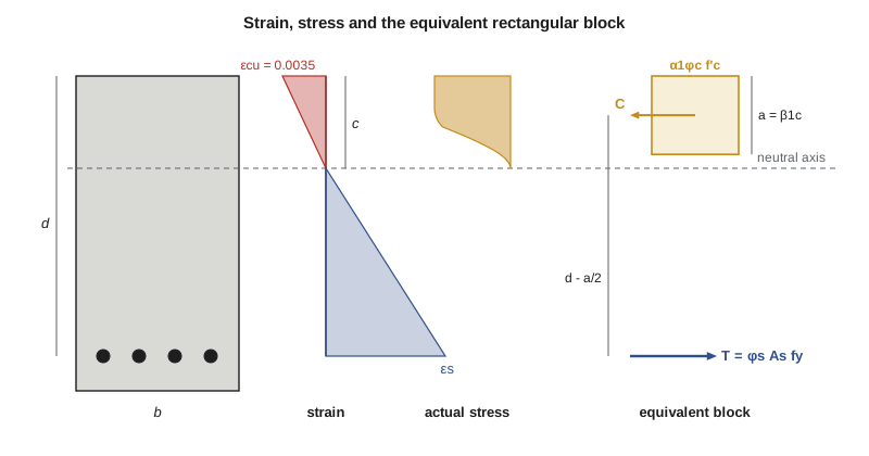
- Plane sections remain plane, so strain varies linearly over the depth.
- Bond is perfect: the strain in a bar equals the strain in the surrounding concrete.
- The tensile strength of concrete is ignored at the ultimate limit state.
- The maximum usable strain at the extreme compression fibre is 0.0035.
- Steel stress is \(E_s\varepsilon_s\) below yield and \(f_y\) above.
- The concrete compressive stress may be represented by a uniform stress \(\alpha_1\phi_c f'_c\) over a depth \(a = \beta_1 c\).
Resistance of a rectangular section
Consider a rectangular section of width \(b\) and effective depth \(d\), the distance from the compression face to the centroid of the tension steel area \(A_s\). Assume the steel yields. Equilibrium of horizontal forces requires the factored compression in the concrete to equal the factored tension in the steel:
The two forces form a couple with lever arm \(d - a/2\), so
Because the material factors are inside the equations, \(M_r\) is already a factored resistance; there is no further reduction. The lever arm is typically 0.85d to 0.95d for beams, so a quick estimate is \(M_r \approx 0.9 d\,\phi_s A_s f_y\).
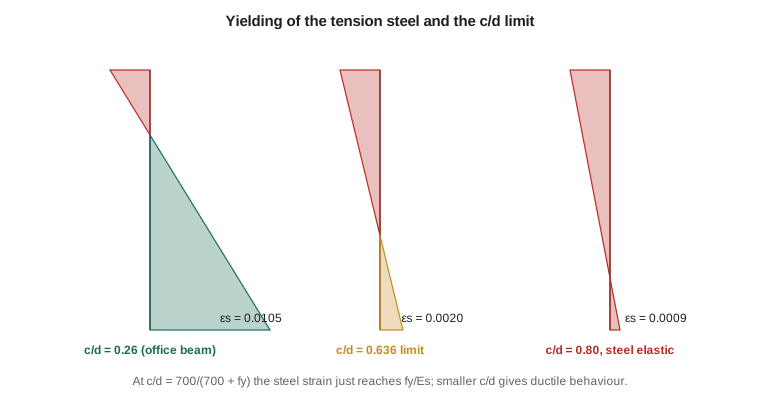
The assumption that the steel yields must be checked. From the linear strain diagram, the strain at the level of the steel is
Keeping the failure ductile
If a beam has too much steel, the concrete crushes before the steel yields and the failure is sudden. Setting \(\varepsilon_s = \varepsilon_y = f_y/E_s\) in the strain relation gives the neutral axis depth at which the steel just reaches yield:
For grade 400 steel the limit is \(c/d \le 0.636\). A23.3 requires that when \(c/d\) exceeds this value the steel is no longer assumed to yield; in flexural members the designer adds compression reinforcement (lesson 4) or enlarges the section rather than relying on unyielded tension steel. The factored resistance of a beam with \(c/d\) near the limit is not reduced by a larger factor, as it is in ACI 318, because the material factors already make concrete-controlled resistance smaller.
A good design target is well inside the ductile range. Beams designed with a moderate amount of steel, about half of the limiting amount, have large ductility, smaller deflections because they are deeper, and room for bars to be placed and compacted properly.
Minimum reinforcement
The opposite problem arises when a beam has very little steel. If the steel cannot carry the force that the concrete was carrying in tension just before cracking, the beam fails as soon as it cracks, as suddenly as plain concrete. Minimum reinforcement prevents this:
where \(b_t\) is the width of the tension zone (the web width for a T-beam in positive bending). The requirement may be waived if the steel provided is at least one third larger than that required by analysis. Slabs follow a different minimum, \(0.002A_g\), covered in lesson 8.
Designing a beam
In design the moment is known and both the section and the steel must be chosen. The usual sequence is:
- Choose the depth. A first estimate is span/12 to span/16 for simply supported beams, checked against the minimum thicknesses for deflection in lesson 5. Widths of 0.4 to 0.6 times the depth suit most beams, and dimensions are rounded to 25 or 50 mm for formwork.
- Estimate \(d\) as \(h\) minus cover, stirrup diameter and half a bar diameter: about \(h - 60\) mm for one layer of bars in an interior beam.
- Solve the moment equation for the required steel area. Substituting the expression for \(a\) into the moment equation gives a quadratic in \(A_s\).
- Select bars, check that they fit, and recompute the resistance with the actual \(d\).
- Check \(c/d\) and the minimum steel.
A convenient form of the solution writes the resistance per unit of \(bd^2\) as a coefficient \(K_r\):
Design aids tabulate \(\rho\) against \(K_r\) for common materials. With a calculator or a short program, solving the quadratic directly is just as quick.
Worked problem
Designing the office floor beam
Design the tension steel for the office floor beam: \(M_f = 302\) kN·m (lesson 1), \(f'_c = 30\) MPa, \(f_y = 400\) MPa, interior exposure. Owen chose \(b = 350\) mm and \(h = 600\) mm (span/12.5), with 30 mm cover to the 10M stirrups and one layer of 25M bars.
Show solution
- Effective depth:
- \[d = 600 - 30 - 11.3 - 25.2/2 = 546\ \text{mm, taken conservatively as } 540\ \text{mm}\]
- Stress block factors: \(\alpha_1 = 0.805\), \(\beta_1 = 0.895\). Required resistance coefficient:
- \[K_r = \frac{302 \times 10^6}{350(540)^2} = 2.96\ \text{MPa}\]
- Solving the quadratic for \(A_s\) (Sofia's program does this) gives \(A_s = 1839\) mm². Try 4-25M, \(A_s = 2000\) mm²:
- \[a = \frac{0.85(2000)(400)}{0.805(0.65)(30)(350)} = 124\ \text{mm} \qquad c = \frac{124}{0.895} = 139\ \text{mm}\]
- \[M_r = 0.85(2000)(400)\Big(540 - \frac{124}{2}\Big) = 325 \times 10^6\ \text{N·mm} = 325\ \text{kN·m} \ge 302\]
- Ductility: \(c/d = 139/540 = 0.256 \le 0.636\), so the steel yields with a large margin. The steel strain is \(0.0035(540 - 139)/139 = 0.0101\), five times the yield strain.
- Minimum steel:
- \[A_{s,min} = \frac{0.2\sqrt{30}}{400}(350)(600) = 575\ \text{mm}^2 < 2000\]
Answer: Use 4-25M bottom bars: \(M_r = 325\) kN·m against \(M_f = 302\) kN·m, with \(c/d = 0.26\). Three 25M bars would give only 252 kN·m.
The program below solves for the required area, tries two bar arrangements and checks the ductility and minimum steel limits. It is the same calculation, but it makes it easy to try other sizes, which Owen does when the architect asks whether the beam could be 50 mm shallower.
import math
# Office floor beam: singly reinforced rectangular section, CSA A23.3
fc, fy = 30.0, 400.0
phic, phis = 0.65, 0.85
b, h, d = 350.0, 600.0, 540.0
Mf = 302e6                        # N.mm, from lesson 1
a1 = max(0.85 - 0.0015 * fc, 0.67)
b1 = max(0.97 - 0.0025 * fc, 0.67)

# Required steel: solve Mf = phis*As*fy*(d - a/2), a = phis*As*fy/(a1*phic*fc*b)
k = (phis * fy) ** 2 / (2 * a1 * phic * fc * b)
A, B, C = k, -phis * fy * d, Mf
As_req = (-B - math.sqrt(B * B - 4 * A * C)) / (2 * A)
print(f"alpha1 = {a1:.3f}, beta1 = {b1:.3f}")
print(f"As required = {As_req:.0f} mm2")

def resistance(As):
    a = phis * As * fy / (a1 * phic * fc * b)
    c = a / b1
    Mr = phis * As * fy * (d - a / 2)
    return a, c, Mr

for n in (3, 4):
    As = n * 500.0                 # 25M bars
    a, c, Mr = resistance(As)
    ok = "OK" if Mr >= Mf else "too small"
    print(f"{n}-25M: As = {As:.0f}, a = {a:.0f} mm, c/d = {c/d:.3f}, Mr = {Mr/1e6:.0f} kN.m  {ok}")
print(f"c/d limit for yielding: {700/(700+fy):.3f}")
As_min = 0.2 * math.sqrt(fc) / fy * b * h
print(f"As,min = {As_min:.0f} mm2")alpha1 = 0.805, beta1 = 0.895 As required = 1839 mm2 3-25M: As = 1500, a = 93 mm, c/d = 0.192, Mr = 252 kN.m too small 4-25M: As = 2000, a = 124 mm, c/d = 0.256, Mr = 325 kN.m OK c/d limit for yielding: 0.636 As,min = 575 mm2
Analysis of an existing section
Sometimes the section and steel are given and the resistance is wanted, for example when checking an existing structure for a change of use. The procedure is the second half of the design steps: compute \(a\) from equilibrium, check that the steel yields, then compute \(M_r\). If \(c/d\) exceeds the limit, the steel stress must be found from strain compatibility, with \(f_s = E_s\varepsilon_s < f_y\), and equilibrium solved for \(c\) by trial or with a quadratic. Lesson 4 automates this with a general strain-compatibility routine.
Worked problem
Checking an existing lintel
An existing 300 × 500 mm lintel in the old maintenance building has 3-20M bottom bars at \(d = 440\) mm and 25 MPa concrete. What is its factored moment resistance?
Show solution
- \(\alpha_1 = 0.85 - 0.0015(25) = 0.8125\), \(\beta_1 = 0.97 - 0.0025(25) = 0.9075\), \(A_s = 900\) mm².
- \[a = \frac{0.85(900)(400)}{0.8125(0.65)(25)(300)} = 77\ \text{mm} \qquad c = 85\ \text{mm} \qquad c/d = 0.19\]
- \[M_r = 0.85(900)(400)\Big(440 - \frac{77}{2}\Big) = 123\ \text{kN·m}\]
Answer: \(M_r = 123\) kN·m, with the steel yielding comfortably.
How the design variables affect resistance
It helps to know which variables matter most. Moment resistance is nearly proportional to the steel area and to the effective depth, because the lever arm stays close to 0.9d. Doubling the steel roughly doubles the resistance until the ductility limit approaches. Increasing the depth by 10 per cent raises the resistance of the same steel by about 10 per cent and, because stiffness grows with the cube of depth, reduces deflection by about a quarter. Concrete strength has a surprisingly small effect: raising it from 30 to 40 MPa shortens the stress block and lengthens the lever arm by only a few per cent. Width matters little for flexural strength but helps with bar placement, shear and ductility.
These sensitivities explain common design habits. Depth is the most efficient way to add flexural strength and stiffness, so architects and engineers negotiate floor-to-floor heights early. Higher-strength concrete is chosen for durability, for columns and for early formwork stripping, rather than to make beams stronger in bending. And when a beam is limited in depth, the designer adds steel and, if the neutral axis becomes too deep, compression steel, which lesson 4 covers.
Practical points
- Keep beam widths and depths consistent across a floor so formwork can be reused; vary the steel rather than the concrete where possible.
- Use bars of one size within a layer, and avoid more than two sizes in one beam.
- Place bars symmetrically about the centreline and leave room for the vertical bars of the column at beam-column joints.
- When the required steel will not fit in one layer, a second layer reduces \(d\); recompute \(d\) to the centroid of all the bars.
- Very lightly reinforced beams are uneconomical in concrete; heavily reinforced beams are congested and deflect less but crack-control and ductility suffer. Moderate steel ratios of 0.5 to 1.5 per cent are the comfortable range.
Common mistakes
MistakeForgetting \(\phi_s\) in the expression for \(a\).
InsteadThe tension force at the ultimate limit state is \(\phi_s A_s f_y\); both the depth of the block and the lever arm use it.
MistakeMeasuring the effective depth to the bottom of the bars.
Instead\(d\) is measured to the centroid of the tension steel.
MistakeIgnoring the c/d limit when adding bars to meet a high moment.
InsteadAbove \(c/d = 0.636\) the steel does not yield; add compression steel or deepen the beam.
MistakeUsing the gross section for strength calculations.
InsteadConcrete in tension is ignored at the ultimate limit state.
Summary and key terms
- A beam passes through uncracked, cracked elastic and ultimate stages; the ultimate stage should be governed by steel yielding.
- With the rectangular block, \(a = \phi_s A_s f_y/(\alpha_1\phi_c f'_c b)\) and \(M_r = \phi_s A_s f_y(d - a/2)\).
- The steel yields if \(c/d \le 700/(700 + f_y)\), which is 0.636 for grade 400.
- Minimum steel \(0.2\sqrt{f'_c}\,b_t h/f_y\) prevents sudden failure at cracking.
- The office beam, 350 × 600 mm with 4-25M, has \(M_r = 325\) kN·m against \(M_f = 302\) kN·m.
- Effective depth
- The distance from the extreme compression fibre to the centroid of the tension reinforcement.
- Cracking moment
- The moment at which the extreme tension fibre reaches the modulus of rupture.
- Neutral axis depth
- The distance from the compression face to the line of zero strain, written c.
- Ductility
- The ability to deform well beyond first yield without losing strength.
- Reinforcement ratio
- The tension steel area divided by bd.
- Factored moment resistance
- Mr, the moment resistance computed with φc and φs applied to the materials.
- c/d limit
- 700/(700 + fy), the neutral axis ratio at which the tension steel just yields.
- Minimum reinforcement
- The smallest steel area that prevents brittle failure at first cracking.
Practice problems
Work each problem on paper first, then reveal the answer to check.
A 300 × 550 mm beam (\(d = 490\) mm) has 3-25M and 30 MPa concrete. Find \(M_r\).
Show answer
\(a = 0.85(1500)(400)/(0.805 \times 0.65 \times 30 \times 300) = 108\) mm; \(M_r = 510\,000(490 - 54) = 222\) kN·m; \(c/d = 0.25\).
What is the c/d limit for grade 500 steel?
Show answer
\(700/1200 = 0.583\).
Find \(A_{s,min}\) for a 400 × 700 mm beam with 35 MPa concrete.
Show answer
\(0.2\sqrt{35}(400)(700)/400 = 828\) mm².
Why does the lever arm \(d - a/2\) change little when steel is added?
Show answer
The block depth \(a\) is small compared with \(d\) for normal steel ratios, so the lever arm stays near 0.9d.
What happens to ductility if the beam is made shallower for the same moment?
Show answer
More steel is needed, the neutral axis drops, the steel strain at failure is smaller, and ductility falls.
Lesson quiz · 5 questions
Score 60% or more to complete this lesson.
Create a free account to save your progress, take quizzes and earn a certificate.