
CIV-330 · Lesson 12 of 12 · 20 min
Footings and the design capstone
Every load in the building ends up in the ground, and footings are where the concrete structure meets the soil. A spread footing is a thick slab that spreads a column load over enough soil area to keep the bearing pressure within what the soil can safely carry. Its design brings together almost everything in this course: one-way and two-way shear, flexure, minimum steel, development length and bearing. This final lesson designs the footing under the office column of lesson 10 and then reviews the complete set of members designed for the operations centre.
Types of footings
- Isolated spread footings support single columns; they are the most common foundation for low-rise buildings on reasonable soil.
- Wall footings are continuous strips under bearing walls and behave as one-way cantilevers on each side of the wall.
- Combined footings support two or more columns, typically where a column is close to a property line and cannot have its own centred footing.
- Mat (raft) foundations cover the whole building footprint and suit weak soils or heavy loads.
- Pile caps transfer column loads to groups of piles when the near-surface soil is too weak; they are designed with strut-and-tie models.
The geotechnical report for the Thunder Bay site describes dense glacial till below about 1.5 m and recommends spread footings founded below the local frost depth, with a factored geotechnical resistance at ULS and a serviceability bearing pressure of 280 kPa net for settlement of 25 mm or less.
Sizing the footing area
The footing area is chosen from the soil's serviceability bearing pressure using specified (unfactored) loads, because that pressure is set to limit settlement. Using the net pressure means the weight of the footing and the soil above it is already accounted for. Under a concentric load the pressure is assumed uniform. The structural design of the concrete then uses the factored column load spread uniformly over the chosen area: the factored net soil pressure \(q_f = P_f/A\).
Footings with moment, from frame action or eccentric columns, have a trapezoidal pressure distribution, and the resultant must stay within the middle third of the footing to keep the whole base in contact with the soil. The interior office column carries a small moment, which Owen ignores for sizing but includes in the punching check of the final design.
Thickness from shear
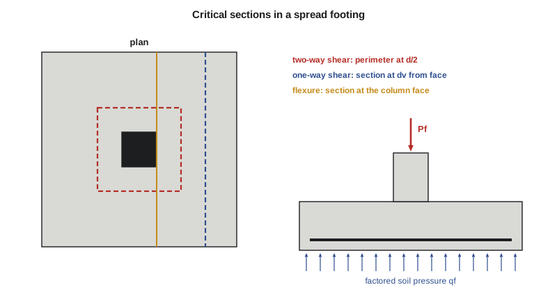
Footings are normally made deep enough to need no shear reinforcement, because stirrups in footings are awkward to place and concrete is cheap. Two shear checks set the depth:
- Two-way (punching) shear on a perimeter at \(d/2\) from the column faces, exactly as for a flat plate in lesson 9. The shear is the factored soil pressure on the area outside the perimeter. Because footings are thick, the size effect factor \(1300/(1000 + d)\) usually applies when \(d\) exceeds 300 mm.
- One-way (beam) shear across the full width at \(d_v\) from the column face, as for a wide beam without stirrups, with \(\beta = 230/(1000 + d_v)\). In large, square footings one-way shear often governs because the size effect bites hard on a deep member without stirrups.
The depth is usually found by trial: assume a thickness, compute both shears, and adjust in steps of 50 mm or 3 in.
Flexure, steel and bearing
The footing bends upward like an inverted cantilever slab on each side of the column. The critical section for moment is at the face of the column (or halfway between the face and the centre for masonry walls, or at the face of a base plate for steel columns). The moment is the soil pressure on the overhang times its lever arm, across the full width. The steel is placed as a uniform mesh in both directions for square footings; in rectangular footings, more of the short-direction steel is concentrated in a central band equal to the footing width.
Minimum steel is \(0.002A_g\) in each direction, as for slabs, with spacing not more than 3 times the thickness or 500 mm. Cover is 75 mm for concrete cast against soil. The bars must develop their strength between the column face and the bar ends, and the column load must transfer into the footing by bearing on the concrete under the column, with the bearing resistance \(0.85\phi_c f'_c A_1\) increased by \(\sqrt{A_2/A_1} \le 2\) because the footing confines the loaded area. Any force above the bearing resistance, and at least \(0.005A_g\) of the column area in any case, is carried by dowels developed in both the column and the footing.
Worked problem
Footing under the office column
Design a square footing for the 500 × 500 mm interior column: \(D = 1700\) kN, \(L = 720\) kN, net SLS bearing pressure 280 kPa, footing concrete \(f'_c = 25\) MPa, 20M bars in two layers, 75 mm cover.
Show solution
- Area: \(A = (1700 + 720)/280 = 8.64\) m², so \(B = 3.0\) m (9.0 m²).
- \[P_f = 1.25(1700) + 1.5(720) = 3205\ \text{kN} \qquad q_f = \frac{3205}{9.0} = 356\ \text{kPa}\]
- Try \(h = 750\) mm, \(d = 750 - 75 - 20 = 655\) mm (average of two layers).
- Two-way shear: \(b_o = 4(500 + 655) = 4620\) mm; \(V_f = 356(9.0 - 1.155^2) = 2729\) kN; \(v_f = 2\,729\,000/(4620 \times 655) = 0.90\) MPa.
- \[v_c = 0.38(0.65)\sqrt{25}\,\frac{1300}{1000 + 655} = 1.235(0.786) = 0.97\ \text{MPa} \ge 0.90\]
- One-way shear: \(d_v = \max(0.9 \times 655,\ 0.72 \times 750) = 590\) mm. The section is \(1250 - 590 = 660\) mm from the edge:
- \[V_f = 356(3.0)(0.660) = 705\ \text{kN} \qquad V_c = 0.65\,\frac{230}{1590}\sqrt{25}(3000)(590) = 832\ \text{kN} \ge 705\]
- Shallower footings fail: at \(h = 700\) mm, punching gives 1.04 MPa against 1.00 MPa.
- Flexure at the column face, cantilever 1.25 m: \(M_f = 356(3.0)(1.25)^2/2 = 835\) kN·m. Strength needs about 3850 mm²; the minimum \(0.002(3000)(750) = 4500\) mm² governs: 15-20M each way at 200 mm.
- Development: 20M bottom bars need \(l_d = 0.45(0.8)(400/5)(19.5) = 562\) mm; available \(1250 - 75 = 1175\) mm.
- Bearing: \(0.85(0.65)(25)(250\,000)(2) = 6906\) kN \(\ge 3205\) kN. The 8-25M column bars are extended as dowels, which exceeds \(0.005A_g = 1250\) mm².
Answer: Footing 3.0 × 3.0 × 0.75 m with 15-20M each way at 200 mm, bottom, and 8-25M dowels. Shear sets the thickness and minimum steel sets the bars.
import math
# Square spread footing under the 500 x 500 interior column, CSA A23.3
fc, fy, phic, phis = 25.0, 400.0, 0.65, 0.85
D, L = 1700.0, 720.0                     # kN, specified column loads
q_sls = 280.0                            # kPa, net serviceability bearing pressure from the geotechnical report
c = 0.5
A_req = (D + L) / q_sls
B = math.ceil(math.sqrt(A_req) * 10) / 10
Pf = 1.25 * D + 1.5 * L
qf = Pf / B**2
print(f"service load {D+L:.0f} kN -> area {A_req:.2f} m2 -> B = {B:.1f} m; Pf = {Pf:.0f} kN, qf = {qf:.0f} kPa")

def checks(h):
    d = h - 75 - 20                       # 75 mm cover cast against soil, two layers of 20M
    rt = math.sqrt(fc)
    # two-way shear at d/2 from the column face
    b0 = 4 * (c * 1000 + d)
    Vf2 = qf * (B**2 - ((c * 1000 + d) / 1000) ** 2)
    vf = Vf2 * 1e3 / (b0 * d)
    vc = min(3 * 0.19, 4 * d / b0 + 0.19, 0.38) * phic * rt
    if d > 300: vc *= 1300 / (1000 + d)          # size effect for deep slabs and footings
    # one-way shear at dv from the column face (no stirrups)
    dv = max(0.9 * d, 0.72 * h)
    Vf1 = qf * B * ((B - c) / 2 - dv / 1000)
    beta = 230 / (1000 + dv)
    Vc1 = phic * beta * rt * B * 1000 * dv / 1e3
    return d, vf, vc, Vf1, Vc1

h_use = None
for h in (550, 600, 650, 700, 750):
    d, vf, vc, Vf1, Vc1 = checks(h)
    ok = vf <= vc and Vf1 <= Vc1
    if ok and h_use is None: h_use = h
    print(f"h = {h}: d = {d}, punching vf = {vf:.2f} vs vc = {vc:.2f} MPa; "
          f"one-way Vf = {Vf1:.0f} vs Vc = {Vc1:.0f} kN  {'OK' if ok else '-'}")

h = h_use; d = h - 95
print(f"use h = {h} mm")
Mf = qf * B * ((B - c) / 2) ** 2 / 2            # at the column face
a1 = 0.85 - 0.0015 * fc
k = (phis * fy) ** 2 / (2 * a1 * phic * fc * B * 1000)
As = (phis * fy * d - math.sqrt((phis * fy * d) ** 2 - 4 * k * Mf * 1e6)) / (2 * k)
As = max(As, 0.002 * B * 1000 * h)
n = math.ceil(As / 300)
print(f"flexure: Mf = {Mf:.0f} kN.m, As = {As:.0f} mm2 -> {n}-20M each way at {B*1000/n:.0f} mm")
# bearing at the column-footing interface (A2/A1 effect capped at 2)
Br = 0.85 * phic * fc * 0.25e6 * min(math.sqrt(B**2 / c**2), 2) / 1e3
print(f"bearing on the footing: Br = {Br:.0f} kN vs Pf = {Pf:.0f} kN")
ld = 0.45 * 0.8 * fy / math.sqrt(fc) * 19.5    # 20M bottom bars, k4 = 0.8
print(f"20M bars: length from column face to bar end {(B - c)/2*1000 - 75:.0f} mm vs ld = {ld:.0f} mm")service load 2420 kN -> area 8.64 m2 -> B = 3.0 m; Pf = 3205 kN, qf = 356 kPa h = 550: d = 455, punching vf = 1.66 vs vc = 1.10 MPa; one-way Vf = 898 vs Vc = 652 kN - h = 600: d = 505, punching vf = 1.40 vs vc = 1.07 MPa; one-way Vf = 850 vs Vc = 701 kN - h = 650: d = 555, punching vf = 1.20 vs vc = 1.03 MPa; one-way Vf = 802 vs Vc = 747 kN - h = 700: d = 605, punching vf = 1.04 vs vc = 1.00 MPa; one-way Vf = 754 vs Vc = 791 kN - h = 750: d = 655, punching vf = 0.90 vs vc = 0.97 MPa; one-way Vf = 706 vs Vc = 832 kN OK use h = 750 mm flexure: Mf = 835 kN.m, As = 4500 mm2 -> 15-20M each way at 200 mm bearing on the footing: Br = 6906 kN vs Pf = 3205 kN 20M bars: length from column face to bar end 1175 mm vs ld = 562 mm
The trial loop shows the size effect at work: a 700 mm footing fails punching by only 4 per cent, while the 750 mm footing passes both checks. Owen also notes that the dowels must develop in compression inside the footing, about 480 mm for 25M bars in 25 MPa concrete, which the 655 mm effective depth provides; they are hooked at the bottom so they can be tied to the mat.
Design review: the operations centre
Over twelve lessons the team has designed a representative member of every type in the operations centre. The table collects the results.
| Member | Size | Main reinforcement | Governing check |
|---|---|---|---|
| Office floor beam | 350 × 600 mm | 4-25M bottom, 10M stirrups @ 325 | Flexure; deflection with continuity |
| Depth-limited office beam | 350 × 500 mm | 7-25M bottom, 2-25M top | Flexure (doubly reinforced) |
| Garage T-beam | 450 × 700 mm, bf 4050 | 5-30M bottom | Flexure |
| Maintenance bay girder | 400 × 700 mm | 10M stirrups @ 200 near hoist | Shear |
| Garage parking slab | 200 mm | 15M @ 200 top, minimum elsewhere | Crack control |
| Administration flat plate | 250 mm | 15M @ 170 top in column strips | Punching shear |
| Office interior column | 500 × 500 mm | 8-25M, 10M ties | Axial load |
| Garage interior column | 400 × 400 mm, 6 m | 8-20M, 10M ties @ 300 | Slenderness |
| Interior column footing | 3.0 × 3.0 × 0.75 m | 15-20M each way | Two-way and one-way shear |
The governing checks are spread across the course, which is typical. Flexure decides beams, but deflection, crack control, punching shear and slenderness each govern somewhere. A designer who checks only strength would have under-designed the parking slab, the flat plate and the tall garage column.
From calculations to construction
Calculations are only part of a design. The team now turns to the work that gets a concrete building built correctly:
- Drawings and schedules. Beam, column and footing schedules, slab reinforcement plans and typical details communicate the design to the contractor and the reinforcing steel detailer.
- Specifications. The concrete specification sets strength, exposure class, air content, aggregate size, curing and testing; the reinforcing specification sets grades, coating and placing tolerances.
- Independent checking. Kestrel Bay's practice is that a second engineer checks every calculation package, independently where the consequences of an error are serious. Sofia's programs are checked against hand calculations for at least one case each, as this course has done.
- Shop drawing review. The detailer's bar placing drawings and bending schedules are reviewed against the design, especially laps, hooks and congested joints.
- Field review. Engineers inspect reinforcing before concrete is placed, because once the concrete is in, errors are expensive or impossible to correct. Cover, bar sizes and spacing, lap lengths and the support of top bars are the usual items.
- Construction loads and shoring. Slabs must not be loaded beyond their strength at early ages; reshoring schedules and minimum stripping strengths protect young concrete, especially flat plates.
Where reinforced concrete design goes next
This course has covered the members of an ordinary building under gravity loads. Further courses build on it: prestressed concrete, which precompresses members to control cracking and span farther; seismic design, with ductile detailing, capacity design and the behaviour of shear walls and moment frames; strut-and-tie modelling for deep beams, corbels and pile caps; torsion and walls; and the durability and repair of existing structures. All of them rest on the same foundation of equilibrium, strain compatibility and material behaviour that this course has used from the first lesson.
Common mistakes
MistakeSizing the footing area with factored loads.
InsteadArea comes from service loads and the bearing pressure; factored loads are used for concrete design.
MistakeIncluding the footing self-weight in the factored pressure for shear and flexure.
InsteadSelf-weight and soil above are balanced by their own reaction; use the column load only, with net pressures.
MistakeChecking only punching shear.
InsteadOne-way shear often governs large footings; check both.
MistakeForgetting to check bar development in short footing projections.
InsteadFooting bars must develop between the column face and the bar end; use smaller bars or hooks if needed.
Summary and key terms
- Footing area comes from specified loads and the serviceability or allowable bearing pressure; concrete design uses the factored net soil pressure.
- Thickness is set by two-way shear at \(d/2\) and one-way shear near the column, usually without shear reinforcement.
- Flexure is checked at the column face; minimum slab steel often governs in footings.
- Bars must develop between the column face and the bar end; column loads transfer by bearing and dowels.
- The office footing is 3.0 × 3.0 × 0.75 m with 15-20M each way.
- Across the project, flexure, deflection, crack control, shear, punching and slenderness each governed a member.
- Spread footing
- A slab under a column or wall that spreads the load over enough soil area.
- Net bearing pressure
- Soil pressure in excess of the overburden, used to size footings.
- Factored soil pressure
- The factored column load divided by the footing area, used for concrete design.
- Dowel
- A bar extending from a footing into a column to transfer force across the interface.
- Combined footing
- A footing supporting two or more columns.
- Mat foundation
- A single thick slab supporting a whole building.
- Pile cap
- A thick block that transfers a column load to a group of piles.
- Bearing strength
- The resistance of concrete to a concentrated load, increased when the loaded area is confined.
Practice problems
Work each problem on paper first, then reveal the answer to check.
A column carries \(D = 900\) kN and \(L = 400\) kN on soil with a net SLS pressure of 250 kPa. Find the side of a square footing.
Show answer
\(A = 1300/250 = 5.2\) m², so \(B = 2.3\) m.
For that footing, find \(q_f\).
Show answer
\(P_f = 1125 + 600 = 1725\) kN; \(q_f = 1725/5.29 = 326\) kPa.
Why are footings made deep enough to avoid stirrups?
Show answer
Stirrups are hard to place in footings, and a little more concrete is cheaper than the labour.
Where is the critical section for flexure under a concrete column?
Show answer
At the face of the column.
Name two members in the project where a serviceability check governed.
Show answer
The garage parking slab (crack control) and the office floor beam (deflection, before continuity was included).
Lesson quiz · 5 questions
Score 60% or more to complete this lesson.
Create a free account to save your progress, take quizzes and earn a certificate.