
CHE-312 · Lesson 2 of 12 · 26 min
Steady conduction and thermal resistance networks
Northgate's expansion adds 1.8 km of new transmission main between the plant and Riverside General Hospital. Part of it runs through an existing utility tunnel and part is buried. The pipe will be pre-insulated: a steel carrier pipe, a thick layer of polyurethane foam, and a polyethylene casing, factory-bonded into one unit. Kofi needs the heat loss per metre for the tender documents, and Graham wants to know how hot the casing will run in the tunnel, where maintenance crews work. Both questions are answered by treating the pipe as a set of thermal resistances in series, the most useful single idea in heat transfer.
The heat equation and one-dimensional conduction
Fourier's law gives the flux when the temperature field is known. To find the field itself, an energy balance is applied to a small element of material. In Cartesian coordinates with constant conductivity, the result is the heat equation:
where \(\dot q\) is the volumetric generation rate (W/m³) and \(\alpha\) the thermal diffusivity (m²/s). This lesson deals with the simplest and most common case: steady state, no generation, and temperature varying in one direction only. In a plane wall the equation reduces to \(d^2T/dx^2 = 0\), so the temperature is linear through the wall. In a long cylinder, where heat flows radially, it becomes \(\frac{1}{r}\frac{d}{dr}\big(r\frac{dT}{dr}\big) = 0\), whose solution varies with \(\ln r\); in a sphere the temperature varies with \(1/r\).
Thermal resistance
In each of these cases the heat rate is proportional to the overall temperature difference, so we can define a thermal resistance by analogy with Ohm's law, with temperature difference playing the role of voltage and heat rate the role of current: \(q = \Delta T / R\). The standard resistances are:
| Element | Resistance R (K/W) |
|---|---|
| Plane wall, thickness L, area A | \(L/(kA)\) |
| Cylindrical shell, radii r₁ to r₂, length L | \(\ln(r_2/r_1)/(2\pi k L)\) |
| Spherical shell, radii r₁ to r₂ | \((1/r_1 - 1/r_2)/(4\pi k)\) |
| Convection over area A | \(1/(hA)\) |
| Radiation (linearized) over area A | \(1/(h_r A)\) |
| Contact between surfaces of area A | \(R''_{t,c}/A\) |
Resistances in series add; resistances in parallel combine as reciprocals. Convection and radiation from the same surface to air and surroundings at the same temperature act in parallel, so their coefficients add. Once the network is drawn, the problem becomes arithmetic, and the relative sizes of the resistances show at once which layer controls the heat flow and where design effort should go.
For pipes it is convenient to work per metre of length, writing \(R'\) in m·K/W and \(q'\) in W/m. For walls, a resistance per unit area, \(R''\) in m²·K/W, is the familiar insulation RSI value. The overall heat transfer coefficient \(U\) is the inverse of the total resistance per unit area: \(q = UA\,\Delta T\), with \(UA = 1/R_{\text{tot}}\). For a cylinder, \(U\) must always be stated with the area it is based on, inside or outside, since the two differ.
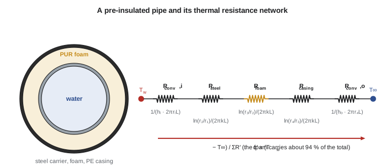
The pre-insulated pipe
The new main uses a DN200 carrier, outside diameter 219.1 mm and wall 5.9 mm, inside a 315 mm polyethylene casing. Standards for these bonded pipe systems, such as EN 253 for directly buried hot-water networks, which is used in Canada and the United States as well as Europe, limit the aged conductivity of the foam; typical manufacturers' values are around 0.022 to 0.029 W/m·K at a mean foam temperature of 50 °C. We take 0.027 W/m·K as a conservative aged value. Water at 110 °C flows inside, and the tunnel air is at 20 °C.
# Thermal resistance networks: a pre-insulated district heating pipe in a utility tunnel
import math
def R_cyl(r1, r2, k, L=1.0):  return math.log(r2 / r1) / (2 * math.pi * k * L)
def R_conv(r, h, L=1.0):      return 1.0 / (h * 2 * math.pi * r * L)

# DN200 steel carrier pipe, polyurethane foam, polyethylene casing (per 1 m length of pipe)
r_i, r_o = 0.20730 / 2, 0.21910 / 2           # steel inside and outside radius (m)
r_f, r_c = 0.3052 / 2, 0.3150 / 2             # foam outside radius, casing outside radius (m)
k_st, k_pur, k_pe = 50.0, 0.027, 0.43         # W/m.K (foam value is a typical aged value)
h_i, h_o = 5000.0, 9.0                        # water side; tunnel air, convection plus radiation
T_w, T_air = 110.0, 20.0

parts = [("water film", R_conv(r_i, h_i)), ("steel wall", R_cyl(r_i, r_o, k_st)),
         ("PUR foam", R_cyl(r_o, r_f, k_pur)), ("PE casing", R_cyl(r_f, r_c, k_pe)),
         ("outside air", R_conv(r_c, h_o))]
R_tot = sum(R for _, R in parts)
q = (T_w - T_air) / R_tot
print(f"heat loss q' = {q:.1f} W/m   (total R' = {R_tot:.3f} m.K/W)")
T = T_w
for name, R in parts:
    print(f"  {name:12s} R' = {R:8.5f} m.K/W  ({R/R_tot:6.1%})   T after = {T - q*R:7.2f} C")
    T -= q * R
print(f"overall U based on casing area: {1/(R_tot*2*math.pi*r_c):.3f} W/m2.K")
print(f"loss over a 1.8 km supply line: {q*1800/1000:.1f} kW")

# Composite plane wall with a contact resistance: a boiler casing panel
layers = [("steel skin", 0.003, 45.0), ("mineral wool", 0.10, 0.045), ("aluminum jacket", 0.001, 200.0)]
Rc = 2e-4                                  # contact resistance between skin and wool, m2.K/W (assumed)
R_flat = 1/30.0 + sum(L/k for _, L, k in layers) + Rc + 1/10.0
print(f"\nboiler casing: U = {1/R_flat:.3f} W/m2.K, flux at 250 C inside, 24 C hall = {(250-24)/R_flat:.0f} W/m2")

# Critical radius: insulating a small tube and an electrical cable
for name, k, h, r0 in (("10 mm copper tube, elastomeric foam", 0.040, 8.0, 0.005),
                       ("cable with PVC jacket", 0.16, 10.0, 0.004)):
    r_cr = k / h
    print(f"{name}: r_cr = {r_cr*1000:.1f} mm (bare radius {r0*1000:.1f} mm)")
    for t in (0, 2, 5, 10, 20, 40):
        r2 = r0 + t / 1000
        R = (math.log(r2 / r0) / (2*math.pi*k) if t else 0) + 1/(h*2*math.pi*r2)
print(f" thickness {t:2d} mm -> q' = {50/R:6.2f} W/m for a 50 K difference")heat loss q' = 43.3 W/m (total R' = 2.078 m.K/W)
water film R' = 0.00031 m.K/W ( 0.0%) T after = 109.99 C
steel wall R' = 0.00018 m.K/W ( 0.0%) T after = 109.98 C
PUR foam R' = 1.95371 m.K/W ( 94.0%) T after = 25.37 C
PE casing R' = 0.01170 m.K/W ( 0.6%) T after = 24.86 C
outside air R' = 0.11228 m.K/W ( 5.4%) T after = 20.00 C
overall U based on casing area: 0.486 W/m2.K
loss over a 1.8 km supply line: 78.0 kW
boiler casing: U = 0.424 W/m2.K, flux at 250 C inside, 24 C hall = 96 W/m2
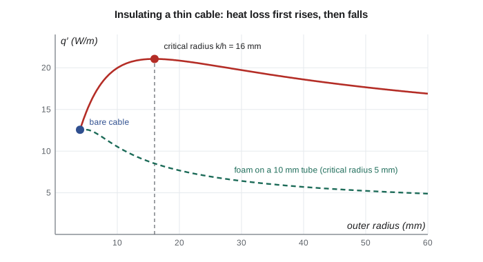
10 mm copper tube, elastomeric foam: r_cr = 5.0 mm (bare radius 5.0 mm)
thickness 0 mm -> q' = 12.57 W/m for a 50 K difference
thickness 2 mm -> q' = 11.96 W/m for a 50 K difference
thickness 5 mm -> q' = 10.53 W/m for a 50 K difference
thickness 10 mm -> q' = 8.78 W/m for a 50 K difference
thickness 20 mm -> q' = 6.94 W/m for a 50 K difference
thickness 40 mm -> q' = 5.44 W/m for a 50 K difference
cable with PVC jacket: r_cr = 16.0 mm (bare radius 4.0 mm)
thickness 0 mm -> q' = 12.57 W/m for a 50 K difference
thickness 2 mm -> q' = 16.36 W/m for a 50 K difference
thickness 5 mm -> q' = 19.42 W/m for a 50 K difference
thickness 10 mm -> q' = 20.98 W/m for a 50 K difference
thickness 20 mm -> q' = 20.45 W/m for a 50 K difference
thickness 40 mm -> q' = 18.20 W/m for a 50 K differenceWorked problem
Heat loss from the pre-insulated main in the tunnel
Find the heat loss per metre and the casing surface temperature. Use an inside coefficient of 5000 W/m²·K, steel k = 50 W/m·K, foam k = 0.027 W/m·K, polyethylene k = 0.43 W/m·K and an outside combined convection and radiation coefficient of 9 W/m²·K. The radii are 103.65, 109.55, 152.6 and 157.5 mm.
Show solution
- Inside convection: \(R'_1 = 1/(5000 \cdot 2\pi \cdot 0.10365) = 0.00031\) m·K/W.
- Steel: \(R'_2 = \ln(109.55/103.65)/(2\pi \cdot 50) = 0.00018\) m·K/W.
- Foam: \(R'_3 = \ln(152.6/109.55)/(2\pi \cdot 0.027) = 1.954\) m·K/W.
- Casing: \(R'_4 = \ln(157.5/152.6)/(2\pi \cdot 0.43) = 0.0117\) m·K/W.
- Outside: \(R'_5 = 1/(9 \cdot 2\pi \cdot 0.1575) = 0.112\) m·K/W; total \(R' = 2.078\) m·K/W.
- \[q' = \frac{110 - 20}{2.078} = 43.3\ \text{W/m}, \qquad T_{\text{casing}} = 20 + 43.3(0.112) = 24.9\ ^\circ\text{C}\]
Answer: The foam carries 94 percent of the resistance; the water film and the steel together carry less than 0.03 percent, so their exact values hardly matter. The casing runs only about 5 K above the tunnel air, which answers Graham's question about worker safety. Over the 1.8 km line the loss is about 78 kW, a small fraction of the line's capacity.
The temperatures at each interface, printed by the program, show the same story: almost the whole 90 K drop occurs across the foam. This is typical of insulated systems, and it means that the outside coefficient, which is hard to know precisely in a tunnel, has only a modest effect on the loss. Doubling it to 18 W/m²·K would reduce the outside resistance from 0.112 to 0.056 m·K/W and raise the loss by less than 3 percent.
Composite walls and contact resistance
A boiler casing is a layered wall: an inner steel skin, mineral wool insulation and a thin aluminum outer jacket. Where two solid surfaces are pressed together, they touch only at the peaks of their roughness, and the gaps between are filled with air or a coating. The result is a thermal contact resistance \(R''_{t,c}\), typically 10⁻⁵ to 10⁻³ m²·K/W for metal joints, depending on roughness, pressure and any interstitial material. It matters most where the other resistances are small, such as electronic components bolted to heat sinks, and is usually negligible next to an insulation layer.
Worked problem
A boiler casing panel
Gas inside the casing is at 250 °C with an inside coefficient of 30 W/m²·K; the hall air is at 24 °C with an outside coefficient of 10 W/m²·K. The layers are 3 mm steel (k = 45), 100 mm mineral wool (k = 0.045) and 1 mm aluminum (k = 200), with a contact resistance of 2 × 10⁻⁴ m²·K/W between the steel and the wool. Find U and the heat flux.
Show solution
- Resistances per unit area: \(1/30 = 0.0333\); \(0.003/45 = 0.00007\); \(0.10/0.045 = 2.222\); \(0.001/200 = 0.000005\); contact \(0.0002\); \(1/10 = 0.100\).
- Total \(R'' = 2.356\) m²·K/W.
- \[U = \frac{1}{2.356} = 0.424\ \text{W/m}^2\text{·K}, \qquad q'' = 0.424(250 - 24) = 96\ \text{W/m}^2\]
Answer: The contact resistance is less than 0.01 percent of the total and could have been ignored. The wool is 94 percent. If water got into the wool during a roof leak, its conductivity could rise several-fold, which is why wet insulation is one of the first things a thermal survey looks for.
The critical radius of insulation
Adding insulation to a plane wall always reduces heat loss. On a cylinder it need not, because the insulation also increases the outside surface area. The conduction resistance rises with \(\ln(r_2/r_1)\) while the outside convection resistance falls as \(1/r_2\). Setting the derivative of the total resistance to zero shows that the heat loss is a maximum when the outside radius equals the critical radius
For an elastomeric foam with k = 0.04 W/m·K in still air (h ≈ 8 W/m²·K), the critical radius is 5 mm, so any insulation on a tube larger than 10 mm in diameter reduces the loss, and the effect is irrelevant for Northgate's pipes. For an electrical cable with a PVC jacket (k ≈ 0.16 W/m·K) and h ≈ 10 W/m²·K, the critical radius is 16 mm, larger than the conductor. Here the effect is useful: a jacket of the right thickness lets the cable shed more heat than a bare wire would, so it can carry more current for the same conductor temperature.
Choosing an insulation thickness
Beyond the critical radius, more insulation always helps, but with diminishing returns: the resistance of a cylindrical layer grows only with the logarithm of its outer radius. The economic thickness balances the cost of insulation, which grows faster than linearly with thickness, against the value of the heat saved over the system's life. Codes and standards set minimum thicknesses for building piping, and district energy suppliers offer pre-insulated pipe in two or three insulation series with progressively thicker foam. For a line operating year-round at 110 °C, the thicker series usually pays back, especially when heat is valued at its marginal cost in winter.
In Canada, piping insulation in buildings is governed by the National Energy Code of Canada for Buildings as adopted by each province, which tabulates minimum thicknesses by fluid temperature and pipe size, with adjustments for insulation conductivity. Buried district energy pipes are specified by the utility, usually by reference to European product standards and the manufacturer's insulation series. Manitoba Hydro and other utilities run programs that can support insulation upgrades in older plants.
The resistance concept also exposes a hidden problem: thermal bridges. A pipe support, a valve body or an anchor that passes through the insulation provides a parallel path of low resistance. In a building envelope, steel studs or slab edges do the same thing. Because parallel resistances combine as reciprocals, even a small area of bridge can carry a large share of the heat. Thermal imaging finds these bridges quickly, and Lesson 4 shows how to calculate them when the heat flow is no longer one-dimensional.
Common mistakes
MistakeAdding radial resistances using L/(kA) with an average area.
InsteadUse ln(r₂/r₁)/(2πkL) for cylindrical layers.
MistakeStating U for a pipe without saying which area it is based on.
InsteadU based on inside and outside areas differs; always state the reference area.
MistakeAdding convection and radiation resistances in series.
InsteadFrom the same surface to the same temperature they act in parallel; add the coefficients.
MistakeAssuming more insulation always reduces loss.
InsteadOn a cylinder smaller than the critical radius, a thin layer increases the loss.
MistakeSpending effort on small resistances.
InsteadThe largest resistance controls the heat flow; refine it first.
Summary and key terms
- Steady one-dimensional conduction gives linear, logarithmic and 1/r temperature profiles in walls, cylinders and spheres.
- Thermal resistances L/(kA), ln(r₂/r₁)/(2πkL), 1/(hA) and contact resistances combine like electrical resistances.
- For the pre-insulated main, the foam carries 94 percent of the resistance and the loss is about 43 W/m.
- Contact resistance matters only when the other resistances are small.
- The critical radius k/h limits when insulation reduces heat loss on a cylinder; it matters for cables, not large pipes.
- Thermal bridges act as parallel paths and can dominate the loss.
- Heat equation
- The differential equation for the temperature field obtained from an energy balance on an element.
- Thermal diffusivity
- α = k/(ρc_p), the ratio of conduction to thermal storage.
- Thermal resistance
- The ratio of temperature difference to heat rate for a path, in K/W.
- Overall heat transfer coefficient
- U = 1/(R_tot A), relating heat rate to overall temperature difference.
- Contact resistance
- The extra resistance at an interface between solids caused by imperfect contact.
- Critical radius
- The outer radius of cylindrical insulation at which heat loss is greatest, k/h.
- RSI value
- Thermal resistance per unit area in m²·K/W.
- Pre-insulated pipe
- A carrier pipe, foam insulation and outer casing bonded into one unit.
- Thermal bridge
- A path of low resistance through an insulation layer.
Practice problems
Work each problem on paper first, then reveal the answer to check.
Find the resistance per metre of a 50 mm thick foam layer (k = 0.03 W/m·K) on a pipe of 100 mm outside diameter.
Show answer
ln(100/50)/(2π × 0.03) = 3.68 m·K/W.
A wall has R″ = 3.5 m²·K/W. Find U and the heat flux for a 50 K difference.
Show answer
U = 0.286 W/m²·K; q″ = 14.3 W/m².
In the program, raise the foam conductivity to 0.033 W/m·K (older pipe). Find the new loss.
Show answer
About 52.8 W/m.
Find the critical radius for insulation with k = 0.05 W/m·K and h = 5 W/m²·K.
Show answer
10 mm.
A thermal bridge with R = 0.5 K/W is in parallel with insulation of R = 5 K/W. What fraction of the heat goes through the bridge?
Show answer
About 91 percent.
Why does the water-side coefficient hardly affect the pipe's heat loss?
Show answer
Its resistance is a tiny fraction of the foam's.
Lesson quiz · 5 questions
Score 60% or more to complete this lesson.
Create a free account to save your progress, take quizzes and earn a certificate.