
CHE-312 · Lesson 11 of 12 · 30 min
Radiation exchange between surfaces
Lesson 10 described how single surfaces emit and absorb. Engineering problems involve several surfaces that see each other: the burner floor, water-tube walls and refractory of a furnace; a pipe inside a protective sleeve; a thermocouple inside a hot duct; the panes of a window. How much radiation leaving one surface reaches another depends on their geometry, and how much of it is absorbed depends on their properties. This lesson develops the view factor, which captures the geometry, and the radiation network method, which combines geometry and properties for gray, diffuse surfaces. It finishes with radiation shields, the thermocouple error in hot gas, and a brief look at radiating gases.
The view factor
The view factor \(F_{ij}\) is the fraction of the radiation leaving surface \(i\) that strikes surface \(j\) directly. It depends only on geometry, assuming diffuse emission and reflection. For two small areas, it follows from the cosine law of diffuse emission; for finite surfaces it is an integral over both areas, evaluated once and tabulated or given by formulas for common shapes. Three rules make view factors much easier to handle in practice.
The reciprocity relation, \(A_iF_{ij} = A_jF_{ji}\), lets one view factor be found from another. The summation rule, \(\sum_j F_{ij} = 1\) over all surfaces of an enclosure, follows because all radiation leaving a surface must go somewhere. A flat or convex surface cannot see itself, so \(F_{ii} = 0\); a concave surface can, so \(F_{ii} > 0\). With these rules, a few known view factors often give all the others. For example, a small convex object fully enclosed by a large surface has \(F_{12} = 1\), and reciprocity then gives \(F_{21} = A_1/A_2\).
For long two-dimensional geometries, such as ducts and channels, Hottel's crossed-strings method gives view factors from lengths alone: imagine strings stretched between the edges of the two surfaces, and \(F_{12} = (\text{sum of crossed strings} - \text{sum of uncrossed strings})/(2 \times \text{length of surface 1})\). For three-dimensional shapes, formulas exist for parallel coaxial disks, aligned parallel rectangles, perpendicular rectangles with a common edge, concentric cylinders and spheres and many more, and charts present the most useful.
| Geometry | View factor |
|---|---|
| Small convex body 1 inside enclosure 2 | \(F_{12} = 1,\ F_{21} = A_1/A_2\) |
| Infinite parallel plates | \(F_{12} = F_{21} = 1\) |
| Long concentric cylinders (inner 1, outer 2) | \(F_{12} = 1,\ F_{21} = r_1/r_2,\ F_{22} = 1 - r_1/r_2\) |
| Coaxial parallel disks of radii r₁, r₂, spacing L | \(F_{12} = \tfrac12\big[S - \sqrt{S^2 - 4(r_2/r_1)^2}\big],\ S = 1 + \frac{1 + (r_2/L)^2}{(r_1/L)^2}\) |
| Long equilateral triangular enclosure, any side to another | \(F = 0.5\) |
Blackbody exchange
If all surfaces are black, radiation leaving surface \(i\) is simply its emission, and the net exchange between two surfaces is \(q_{ij} = A_iF_{ij}\sigma(T_i^4 - T_j^4)\). In an enclosure of black surfaces, each surface's net rate is the sum of its exchanges with all the others. Black surfaces are a useful limit and a good model for furnace walls covered in soot or deposits.
Gray, diffuse surfaces and radiosity
Real surfaces reflect part of what arrives, so radiation leaving a surface consists of its emission plus reflected irradiation. The total is the radiosity, \(J = \varepsilon E_b + \rho G\). For an opaque, gray, diffuse surface, with \(\rho = 1 - \varepsilon\), the net radiation leaving the surface can be written in two ways: as emission minus absorption, or as radiosity minus irradiation. Eliminating \(G\) gives
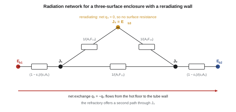
The first equation describes a surface resistance between the blackbody potential and the radiosity; the second a space resistance between the radiosities of two surfaces. Together they turn any enclosure of gray, diffuse, isothermal surfaces into a network that can be solved like an electrical circuit. A black surface has zero surface resistance, so its radiosity equals \(E_b\). An insulated surface that loses no net heat by conduction or convection, such as refractory with good insulation behind it, is called reradiating: its net radiation is zero, so its radiosity floats at whatever value the network gives, and it has no surface resistance in the circuit. Reradiating surfaces matter greatly in furnaces because they redirect radiation toward the heated surface.
Two-surface enclosures
When two surfaces form an enclosure, the network reduces to three resistances in series, giving
For infinite parallel plates this becomes \(q'' = \sigma(T_1^4 - T_2^4)/(1/\varepsilon_1 + 1/\varepsilon_2 - 1)\). For long concentric cylinders or concentric spheres, with \(F_{12} = 1\), it becomes \(q = \sigma A_1(T_1^4 - T_2^4)/[1/\varepsilon_1 + (1 - \varepsilon_2)/\varepsilon_2 \cdot (r_1/r_2)^n]\), with \(n = 1\) for cylinders and 2 for spheres. For a small object in a large enclosure, \(A_1/A_2 \to 0\), and the result reduces to \(\varepsilon_1\sigma A_1(T_1^4 - T_2^4)\), the expression used since Lesson 1.
# Radiation exchange: view factors, two-surface enclosures, shields, a thermocouple in flue gas and a radiosity solver
import math
sigma = 5.670e-8

# 1. View factor between coaxial parallel disks (radius r1 to r2, spacing L)
def F_disks(r1, r2, L):
    R1, R2 = r1 / L, r2 / L
    S = 1 + (1 + R2**2) / R1**2
    return 0.5 * (S - math.sqrt(S**2 - 4 * (R2 / R1)**2))
print(f"disk to disk, both 0.5 m radius, 1 m apart: F12 = {F_disks(0.5, 0.5, 1.0):.3f}; 0.25 m apart: {F_disks(0.5, 0.5, 0.25):.3f}")

# 2. Crossed strings: a long duct 0.4 m wide and 0.3 m deep; floor to one side wall and floor to roof
w, d = 0.4, 0.3
diag = math.hypot(w, d)
F_floor_side = (w + d - diag) / (2 * w)
F_floor_roof = (2 * diag - 2 * d) / (2 * w)
print(f"long duct: F(floor to one side) = {F_floor_side:.3f}, F(floor to roof) = {F_floor_roof:.3f}, sum with two sides = {2*F_floor_side + F_floor_roof:.3f}")

# 3. Two-surface enclosure: a 175 C steam pipe (OD 219 mm) inside a sleeve (ID 300 mm) at 60 C, evacuated or still air ignored
def q_concentric(T1, T2, D1, D2, e1, e2):
    return sigma * math.pi * D1 * (T1**4 - T2**4) / (1 / e1 + (1 - e2) / e2 * D1 / D2)
T1, T2 = 175 + 273.15, 60 + 273.15
for lab, e1, e2 in (("oxidized steel both", 0.80, 0.80), ("pipe wrapped in aluminum foil", 0.05, 0.80), ("both foil", 0.05, 0.05)):
    print(f"pipe in sleeve, {lab:30s}: radiation {q_concentric(T1, T2, 0.219, 0.300, e1, e2):6.1f} W/m")

# 4. Radiation shields between large parallel plates (all emissivities 0.8, shields 0.05 on both faces)
T1, T2 = 600.0, 300.0
q0 = sigma * (T1**4 - T2**4) / (1/0.8 + 1/0.8 - 1)
for N in (0, 1, 2, 4):
    R = (1/0.8 + 1/0.8 - 1) + N * (1/0.05 + 1/0.05 - 1)
    print(f"{N} shields: q'' = {sigma*(T1**4 - T2**4)/R:7.1f} W/m2 ({sigma*(T1**4 - T2**4)/R/q0:5.1%} of unshielded)")

# 5. Thermocouple in a flue duct: true gas temperature from the reading (energy balance on the junction)
h, eps_tc, T_read, T_wall = 80.0, 0.6, 500.0, 400.0
Tg = T_read + eps_tc * sigma * (T_read**4 - T_wall**4) / h
print(f"thermocouple reads {T_read:.0f} K with walls at {T_wall:.0f} K: true gas about {Tg:.0f} K (error {Tg - T_read:.0f} K)")
# with a thin cylindrical radiation shield (emissivity 0.3) around it, the shield sits between gas and wall
eps_s, h_s = 0.3, 80.0
Ts = T_read
for _ in range(200):                     # junction: h(Tg - Tj) = eps_tc sigma (Tj^4 - Ts^4), shield: 2h(Tg - Ts) = eps_s sigma (Ts^4 - Tw^4) (+ junction term ignored)
    Ts = Tg - eps_s * sigma * (Ts**4 - T_wall**4) / (2 * h_s)
Tj = Tg
for _ in range(200):
    Tj = Tg - eps_tc * sigma * (Tj**4 - Ts**4) / h
print(f"  with a shield the junction reads {Tj:.0f} K (error {Tg - Tj:.0f} K); shield at {Ts:.0f} K")

# 6. Radiosity method for a long furnace of equilateral triangular section (each view factor 0.5)
#    surface 1: burner floor 1500 K, eps 0.9; surface 2: water-tube wall 600 K, eps 0.8; surface 3: refractory, reradiating
row1, row2, row3 = [0, .5, .5], [.5, 0, .5], [.5, .5, 0]
F = [row1, row2, row3]
Tsurf, eps, A = [1500.0, 600.0, None], [0.9, 0.8, None], [1.0, 1.0, 1.0]     # areas per 1 m of length (m2)
# unknowns J1, J2, J3; equations: (Eb_i - J_i) eps_i/(1-eps_i) = sum_j F_ij (J_i - J_j) for 1, 2; sum_j F_3j (J3 - Jj) = 0
Eb = [sigma * T**4 if T else 0 for T in Tsurf]
M, b = [list([0.0] * 3) for _ in range(3)], [0.0] * 3
for i in range(2):
    c = eps[i] / (1 - eps[i])
    M[i][i] = c + sum(F[i]); b[i] = c * Eb[i]
    for j in range(3):
        if j != i: M[i][j] -= F[i][j]
M[2] = [-F[2][0], -F[2][1], F[2][0] + F[2][1]]
for col in range(3):                                   # Gaussian elimination
    for r in range(col + 1, 3):
        f = M[r][col] / M[col][col]
        M[r] = [a - f*bb for a, bb in zip(M[r], M[col])]; b[r] -= f * b[col]
J = [0.0]*3
for r in (2, 1, 0):
    J[r] = (b[r] - sum(M[r][c]*J[c] for c in range(r+1, 3))) / M[r][r]
q1 = (Eb[0] - J[0]) * eps[0] / (1 - eps[0]) * A[0]
T3 = (J[2] / sigma) ** 0.25
print(f"furnace: floor delivers {q1/1000:.0f} kW/m, tube wall receives {-(Eb[1]-J[1])*eps[1]/(1-eps[1])/1000:.0f} kW/m, refractory settles at {T3:.0f} K")
q_no_refr = sigma*(1500**4 - 600**4) / ((1-0.9)/0.9 + 1/0.5 + (1-0.8)/0.8)
print(f" if the third wall were open to cold surroundings instead, floor-to-tube exchange alone would be {q_no_refr/1000:.0f} kW/m")disk to disk, both 0.5 m radius, 1 m apart: F12 = 0.172; 0.25 m apart: 0.610 long duct: F(floor to one side) = 0.250, F(floor to roof) = 0.500, sum with two sides = 1.000 pipe in sleeve, oxidized steel both : radiation 763.0 W/m pipe in sleeve, pipe wrapped in aluminum foil : radiation 54.2 W/m pipe in sleeve, both foil : radiation 32.3 W/m 0 shields: q'' = 4592.7 W/m2 (100.0% of unshielded) 1 shields: q'' = 170.1 W/m2 ( 3.7% of unshielded) 2 shields: q'' = 86.7 W/m2 ( 1.9% of unshielded) 4 shields: q'' = 43.7 W/m2 ( 1.0% of unshielded) thermocouple reads 500 K with walls at 400 K: true gas about 516 K (error 16 K) with a shield the junction reads 515 K (error 1 K); shield at 511 K furnace: floor delivers 165 kW/m, tube wall receives 165 kW/m, refractory settles at 1293 K if the third wall were open to cold surroundings instead, floor-to-tube exchange alone would be 118 kW/m
Worked problem
A steam pipe in a sleeve
Where the steam main passes through the boiler-hall wall it runs inside a steel sleeve of 300 mm inside diameter; the pipe's outside diameter is 219 mm. The pipe surface is at 175 °C and the sleeve at 60 °C. Find the radiation exchange per metre with oxidized steel on both (ε = 0.8), with the pipe wrapped in aluminum foil (ε = 0.05), and with foil on both.
Show solution
- Both oxidized: \(q' = \sigma\pi(0.219)(448.15^4 - 333.15^4)/[1/0.8 + (0.25/0.8)(0.219/0.300)] = 763\) W/m.
- Pipe foiled: denominator \(1/0.05 + 0.25(0.73) = 20.18\); \(q' = 54\) W/m.
- Both foiled: denominator \(20 + 19(0.73) = 33.9\); \(q' = 32\) W/m.
Answer: Wrapping the pipe in foil cuts the radiation by about 93 percent; the surface with the lower emissivity controls the exchange, and foiling the smaller surface is the effective choice. Natural convection in the annular gap adds to these figures, but the comparison shows why reflective foils are used in wall penetrations, in vacuum-jacketed piping and in multilayer insulation.
Radiation shields
A radiation shield is a thin sheet of low-emissivity material placed between two surfaces. It adds two surface resistances and one space resistance to the network without conducting heat significantly. Between large parallel plates, each shield with emissivity \(\varepsilon_s\) on both faces adds \(2/\varepsilon_s - 1\) to the denominator. With plates of emissivity 0.8 at 600 K and 300 K, one shield of emissivity 0.05 reduces the flux from 4.59 kW/m² to 170 W/m², under 4 percent of the unshielded value; four shields reduce it to 1 percent. Multilayer insulation on cryogenic tanks and spacecraft, made of dozens of aluminized films in a vacuum, applies this principle.
Radiation error in gas temperature measurement
A thermocouple inserted in a hot gas flowing through a duct with cooler walls gains heat by convection from the gas and loses it by radiation to the walls. At steady state its junction settles below the true gas temperature. An energy balance on the junction gives
Worked problem
Flue gas temperature in the boiler outlet duct
A thermocouple in the flue duct reads 500 K. The duct walls are at 400 K, the convection coefficient to the junction is 80 W/m²·K and the junction emissivity is 0.6. Find the true gas temperature. Then estimate the reading if the junction is surrounded by a thin cylindrical radiation shield of emissivity 0.3, open at both ends to the gas flow.
Show solution
- Unshielded: \(T_g = 500 + 0.6(5.67\times10^{-8})(500^4 - 400^4)/80 = 516\) K; the error is 16 K.
- With the shield, the shield itself is heated by convection on both faces and radiates to the walls; its balance \(2h(T_g - T_s) = \varepsilon_s\sigma(T_s^4 - T_w^4)\) gives \(T_s = 511\) K.
- The junction now radiates to the shield at 511 K instead of the walls at 400 K: \(T_j = 515\) K, an error of about 1 K.
Answer: A radiation-shielded or suction thermocouple, which also raises h by drawing gas past the junction at high velocity, is the standard instrument for accurate gas temperatures in furnaces and stacks. Without one, a combustion analysis based on the measured flue temperature would understate the stack loss.
A furnace with a reradiating wall
For enclosures of three or more surfaces, the network equations are written at each radiosity node and solved together: at a surface with known temperature, \((E_{b,i} - J_i)/R_{\text{surf},i} = \sum_j (J_i - J_j)A_iF_{ij}\); at a reradiating surface, the right side equals zero. The result is a set of linear equations in the radiosities.
Worked problem
Burner floor, tube wall and refractory
A long furnace has a cross-section that is an equilateral triangle of 1 m sides. One side is a burner floor at 1500 K (ε = 0.9), one is a water-tube wall at 600 K (ε = 0.8), and the third is refractory, well insulated and therefore reradiating. Every view factor between sides is 0.5. Find the heat delivered to the tube wall per metre of furnace length and the refractory temperature.
Show solution
- Unknowns \(J_1, J_2, J_3\). Surface resistances: \(0.1/0.9 = 0.111\) and \(0.2/0.8 = 0.25\) m⁻²; space resistances all \(1/(1 \times 0.5) = 2\) m⁻².
- Solving the three node equations gives \(q_1 = -q_2 = 165\) kW per metre, and \(J_3 = \sigma T_3^4\) with \(T_3 = 1293\) K.
- If the third side were instead open to cold surroundings, the direct floor-to-tube exchange alone would be 118 kW per metre.
Answer: The refractory wall adds 40 percent to the heat reaching the tubes by absorbing radiation from the floor and re-emitting it, some of it toward the tubes. Its temperature settles between the two others, closer to the hotter one. This is why boiler furnaces are designed with their refractory and tube surfaces arranged carefully, and why deposits that change surface emissivities alter furnace performance.
Radiating gases
The gases in a furnace are not transparent. Carbon dioxide and water vapour, the main products of combustion, absorb and emit strongly in certain infrared bands, and soot particles in luminous flames emit across the whole spectrum. Air, nitrogen, oxygen and hydrogen are essentially transparent at ordinary temperatures. Gas radiation depends on the gas temperature, the partial pressures of the radiating species and the path length through the gas, expressed through a mean beam length for the enclosure's shape. Hottel's charts give the emissivities of carbon dioxide and water vapour as functions of temperature and the product of partial pressure and path length, with a correction for their overlapping bands. In a large utility boiler furnace, gas and soot radiation deliver most of the heat absorbed by the water walls; in a small duct, gas radiation is often negligible.
Canadian boiler and fired-heater design follows the same methods used throughout North America, and furnace performance checks during commissioning are carried out under the provincial boiler safety authority's requirements. For Northgate, Kofi's furnace model is a check on the boiler manufacturer's guaranteed outlet temperature rather than a design calculation, since the radiant section is supplied as a packaged unit.
Common mistakes
MistakeForgetting that a concave surface can see itself.
InsteadF_ii > 0 for concave surfaces; include it in the summation rule.
MistakeIgnoring reciprocity.
InsteadA_iF_ij = A_jF_ji; use it to find unknown view factors.
MistakeGiving a reradiating surface a surface resistance.
InsteadIts net radiation is zero; its radiosity equals its blackbody emissive power and it has no surface resistance in the circuit.
MistakeFoiling the larger surface of a two-surface enclosure.
InsteadThe smaller surface's emissivity controls more strongly; foil it first.
MistakeTaking a bare thermocouple reading as the gas temperature.
InsteadRadiation to cooler walls makes it read low; correct it or use a shield.
Summary and key terms
- The view factor F_ij is the fraction of radiation leaving i that reaches j; it depends only on geometry.
- Reciprocity, summation and crossed strings find unknown view factors.
- Gray, diffuse surfaces are modelled with surface resistances (1 − ε)/(εA) and space resistances 1/(AF).
- Two-surface enclosures reduce to three series resistances; low-emissivity shields cut exchange sharply.
- Bare thermocouples in hot gas read low; shields reduce the error.
- Reradiating refractory raises the heat delivered to furnace tubes; CO₂, H₂O and soot radiate in flames.
- View factor
- The fraction of radiation leaving one surface that strikes another directly.
- Reciprocity relation
- A_iF_ij = A_jF_ji.
- Summation rule
- The view factors from a surface to all surfaces of an enclosure sum to one.
- Crossed-strings method
- A method for view factors in long two-dimensional geometries using string lengths.
- Radiosity
- The total radiation leaving a surface, emitted plus reflected.
- Surface resistance
- (1 − ε)/(εA), between a surface's blackbody potential and its radiosity.
- Space resistance
- 1/(A_iF_ij), between the radiosities of two surfaces.
- Reradiating surface
- A surface with zero net radiation because it is insulated.
- Radiation shield
- A low-emissivity sheet placed between surfaces to reduce radiation exchange.
- Mean beam length
- An equivalent path length used to calculate gas radiation in an enclosure.
Practice problems
Work each problem on paper first, then reveal the answer to check.
A sphere of 0.1 m diameter is inside a cubical box of 1 m sides. Find F₁₂ and F₂₁.
Show answer
F₁₂ = 1; F₂₁ = 0.0314/6 = 0.0052.
Find the radiation flux between parallel plates at 500 K and 300 K with ε = 0.9 for both.
Show answer
About 2.52 kW/m².
How many shields of ε = 0.05 bring the flux between plates of ε = 0.8 to about 2 percent of the unshielded value?
Show answer
Two.
In the program, raise the thermocouple's h to 250 W/m²·K (suction pyrometer). Find the unshielded error.
Show answer
About 5 K.
In the triangular furnace, what happens to the tube heat if the floor's emissivity falls to 0.6?
Show answer
It falls, to about 124 kW/m, because the floor's surface resistance rises.
Why are CO₂ and H₂O important in furnaces but not in a domestic room?
Show answer
Their radiation depends on partial pressure, path length and temperature, all large in furnaces.
Lesson quiz · 5 questions
Score 60% or more to complete this lesson.
Create a free account to save your progress, take quizzes and earn a certificate.