
BLR-130 · Lesson 9 of 12 · 20 min
Pipe and tube layout basics
Pipe belongs mostly to the pipefitters, but boilermakers handle a great deal of round work: boiler tubes and headers, economizer and superheater elements, nozzle necks on vessels, downcomers and risers, and the short pipe spools that connect boilers and vessels to their piping. On a boiler outage, replacing tubes is often the biggest single task. This lesson covers how pipe and tube are sized, how to find the centre and lay out lines on round work, how to work out cut lengths between fittings, the basic two-piece miter, and the layout of a tube replacement piece. More complex intersections and templates come in Layout and Fitting II.
Pipe and tube sizes
Pipe is sized by its nominal pipe size, NPS, and its schedule. For sizes up to NPS 12, the nominal size is a little smaller than the outside diameter: NPS 6 pipe is 168.3 mm outside diameter. From NPS 14 up, the nominal size equals the outside diameter in inches. The outside diameter of a given NPS is the same for every schedule; the schedule sets the wall thickness, and a heavier schedule has a smaller bore. Metric designations, DN, follow the same outside diameters: DN 150 is NPS 6. Canadian drawings often give pipe in NPS with metric outside diameters and wall thicknesses.
Tube is sized differently: by its actual outside diameter and its wall thickness, in millimetres or in inches and gauge or decimal thickness. Boiler tubes are tube, not pipe. A Riverbend boiler bank tube is 63.5 mm OD with a specified minimum wall. Because tube and pipe of similar nominal size have different outside diameters, a tube fitting will not fit a pipe and a pipe fitting will not fit a tube, and a layout hand must know which is which before ordering or cutting anything.
Finding the centre and laying out lines on round work
Round work has no edges to measure from, so lines must be established. The centre of a pipe end is found with a centre head on a combination square, or by drawing two chords across the end and bisecting them. Lines along a pipe, parallel to its axis, are drawn with a piece of angle laid along the pipe as a straightedge, or with a flexible strip; four such lines at 90 degrees, the quarter lines, are the standard references. Lines around a pipe, square to its axis, are drawn by wrapping a flexible strip, a piece of heavy paper or a wraparound tool around the pipe so that its edges meet exactly, then scribing along the edge.
Quarter lines on a pipe are found by wrapping a strip around it, marking the circumference, folding or measuring the strip into quarters, and transferring the marks. On tube, the same is done with a narrower strip. On a vessel nozzle neck, the quarter lines must align with the vessel's centre lines, so that the flange bolt holes straddle them as lesson 6 described.
Fittings and take-outs
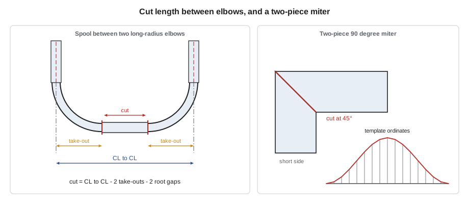
Pipe changes direction through fittings: elbows, tees and reducers. Each fitting has a centre-to-end dimension, called the take-out, from the centre of the fitting to its welding end. A long-radius 90-degree elbow has a centre-line radius of one and a half times its nominal size, and its take-out equals that radius: for NPS 6, 229 mm. A short-radius elbow has a radius equal to its nominal size. A 45-degree long-radius elbow has a shorter take-out. Fitting dimensions come from the fitting standard, ASME B16.9 for butt-welding fittings, and a layout hand uses the table rather than estimating.
The cut length of a pipe between two fittings is the centre-to-centre distance on the drawing, less the take-out of each fitting, less the root opening at each weld. This is the most frequent pipe calculation there is.
The two-piece miter
When no elbow is available, or for large ducts and low-pressure lines, a change of direction can be made with a miter: two pieces of pipe cut at an angle and welded together. A two-piece 90-degree miter has each piece cut at 45 degrees. The cut is not a straight line on the pipe's surface; when the pipe is unrolled, it is a curve. To lay it out, the circumference is divided into equal parts, usually 16, and the distance back from the short side of the cut is calculated at each division. The distances are marked on a wraparound template, or on the pipe itself along the lines at each division, and joined with a smooth curve.
At the short side, the distance is zero; at the long side, it is the outside diameter times the tangent of the cut angle, which for 45 degrees equals the outside diameter. Miters concentrate stress at the inside of the bend and are not used on high-pressure lines without the engineer's approval, but they are common on ducts, vents and low-pressure lines, and the layout method is the basis of the more complex intersections in the next course.
The pulp mill's spool drawings need a straight pipe between two NPS 6 long-radius elbows, 1,500 mm centre to centre, with a 2 mm root opening at each weld, and one two-piece miter on a vent line in the same size. At Riverbend, a boiler bank tube has a damaged section to be cut out over 450 mm and replaced with a new piece, called a dutchman, with a 2 mm root opening at each end.
# Pipe and tube layout: elbow take-out, cut length and a two-piece miter (metric)
from math import tan, cos, radians, pi, gcd
MODE = "mm"

def frac(x, den=16):
    sign = "-" if x < 0 else ""
    n = round(abs(x) * den); whole, rem = divmod(n, den)
    if rem == 0:
        return f"{sign}{whole} in"
    g = gcd(rem, den)
    return f"{sign}{whole} {rem // g}/{den // g} in" if whole else f"{sign}{rem // g}/{den // g} in"

def show(x):
    return f"{x:,.0f} mm" if MODE == "mm" else frac(x)

# 1. cut length of a pipe between two long-radius 90 deg elbows
cc, takeout, gap = 1_500, 229, 2
print("cut length", show(cc - 2 * takeout - 2 * gap))

# 2. two-piece 90 deg miter: ordinates for a wraparound template, 16 divisions
OD, ang = 168.3, 45.0
r = OD / 2
print(f"\nmiter cut on {show(OD)} OD pipe, cut angle {ang:.0f} deg")
for k in range(0, 9):
    phi = 2 * pi * k / 16
    y = r * tan(radians(ang)) * (1 - cos(phi))   # distance back from the short side
    print(f"line {k:>2}: {show(y)}")
print("difference long side to short side:", show(OD * tan(radians(ang))))

# 3. a tube dutchman (replacement piece) for the boiler bank
cutout, tgap = 450, 2
print("\ndutchman length", show(cutout - 2 * tgap), "for a cut-out of", show(cutout))cut length 1,038 mm miter cut on 168 mm OD pipe, cut angle 45 deg line 0: 0 mm line 1: 6 mm line 2: 25 mm line 3: 52 mm line 4: 84 mm line 5: 116 mm line 6: 144 mm line 7: 162 mm line 8: 168 mm difference long side to short side: 168 mm dutchman length 446 mm for a cut-out of 450 mm
The straight pipe is cut to 1,038 mm. The miter ordinates rise from zero at the short side to 168 mm at the long side, which is the pipe's outside diameter, as expected for a 45-degree cut. The dutchman is cut 446 mm long to leave the root opening at both ends.
Tube replacement in boilers
Replacing a section of boiler tube is fitting at its most demanding. The damaged section is cut out with a tube saw or an abrasive cutter, square to the tube's axis, and the tube ends are prepared with a bevelling tool to the weld procedure's bevel and root face. The remaining tube ends must be checked: they may not be in line with each other, since tubes in a bank are rarely perfectly straight, and they may not be round. The dutchman is cut from new tube of the same specification, size and wall, bevelled at both ends, and fitted between the old ends with the root opening the procedure requires, aligned so that the bores match within the allowed offset.
Boiler tube welds are made in tight spaces, often between other tubes, and the fit-up decides whether they can be welded at all. A dutchman that is too long cannot be sprung into place without bending the tubes; one that is too short leaves a gap the welder cannot bridge. Fitters measure the opening at several points around the tube, because the ends may not be square to each other, and cut the dutchman to the shortest measurement less the root openings. Tube alignment clamps hold the dutchman in line while it is tacked. On pressure tubes, the welds are usually examined by radiography, and the inspector checks the fit-up before welding.
Tube work also needs care with identification. Each tube in a boiler has a position, row and number, recorded on the outage drawings. Each replacement piece carries its tube material's heat number and its position, and the record of which piece went where is part of the repair documentation the owner's inspector, Peg Lindqvist at Riverbend, will review.
| Step | What the fitter checks |
|---|---|
| Cut out the damaged section | Cuts are square to the tube axis; the cut-out length is recorded |
| Prepare the ends | Bevel angle and root face match the weld procedure; ends are clean |
| Measure the opening | At four points around the tube, to catch ends that are not square to each other |
| Cut and bevel the dutchman | Same specification, size and wall; length is the shortest opening less two root openings |
| Fit and align | Root opening and bore alignment within the procedure's limits; clamps hold alignment |
| Identify and record | Heat number and tube position recorded for the repair documentation |
Worked problem
Cut length between elbows
A spool has two NPS 4 long-radius elbows 1,000 mm centre to centre. The take-out of each elbow is 152 mm, and the root opening is 2 mm at each weld. What is the cut length of the pipe between them?
Show solution
- Subtract the two take-outs: 1,000 − 2 × 152 = 696 mm.
- Subtract the two root openings: 696 − 2 × 2 = 692 mm.
Answer: Cut the pipe to 692 mm.
Nozzle necks on vessels
A vessel nozzle is a short piece of pipe, the neck, welded into an opening in the shell, with a flange on its outer end. The fitter's part is to get the flange at the right projection from the shell, square to the nozzle's axis, with its bolt holes straddling the right centre lines, and the neck at the right orientation and elevation. The projection is measured from the vessel's centre line or from the shell's outside surface, as the nozzle schedule specifies, and the flange face is checked for square with a level or a square from the shell's reference lines. The layout of the opening in the shell itself, and of the neck's cut where it meets the curved shell, is part of Layout and Fitting II. For now, Kiera's job on V-412 is to cut the necks to length, mark their quarter lines and fit the flanges to them, checking each flange's bolt holes against the nozzle schedule.
Spool identification and checking
A pipe spool is checked as a whole before it leaves the shop: its overall dimensions from flange face to flange face or from weld end to weld end, the orientation of its flange bolt holes, and the angles between its legs. Each spool is marked with its spool number and line number, and its welds with their weld numbers, so that the inspection records can follow each weld. On the pulp mill spools, Kiera checks the face-to-face dimension of each spool against the drawing with a tape and the flange bolt holes with a level across the two holes that should be level, before the spools are tagged for shipping.
Pipe and tube both bring one more fitting issue: the bore. On butt welds in pipe and tube, the inside surfaces at the root should line up, because a step on the inside makes the root pass hard to fuse and leaves a notch. The weld procedure or the piping code sets the allowed internal misalignment, and the fitter checks it with a gauge or by feel at the root before tacking. Where the walls of the two pieces differ, the thicker one is counterbored or tapered so that the bores match.
Common mistakes
MistakeTreating tube and pipe of similar size as interchangeable.
InsteadCheck whether the drawing calls for pipe by NPS or tube by OD before ordering or cutting.
MistakeEstimating a fitting's take-out.
InsteadUse the fitting standard's table.
MistakeForgetting the root openings in a cut length.
InsteadSubtract one root opening for every weld.
MistakeMeasuring a tube opening at one point only.
InsteadMeasure at four points and cut to the shortest less the root openings.
MistakeUsing a miter on a high-pressure line without approval.
InsteadUse miters only where the design allows them.
Summary and key terms
- Pipe is sized by NPS and schedule, with a fixed OD for each NPS; tube is sized by its real OD and wall.
- Lines on round work are established with wraparounds, straightedges and quarter lines.
- A long-radius 90-degree elbow's take-out is 1.5 times its nominal size.
- Cut length between fittings is centre to centre, less the take-outs, less the root openings.
- A two-piece 90-degree miter is laid out with ordinates of (D/2) tan α (1 − cos φ) at equal divisions.
- A tube dutchman is cut to the shortest measured opening less the root openings and fitted in alignment.
- NPS
- Nominal pipe size, the size designation of pipe.
- Schedule
- The wall thickness designation of pipe.
- Take-out
- The distance from a fitting's centre to its welding end.
- Miter
- A change of direction made by cutting pipe at an angle and welding the pieces.
- Dutchman
- A replacement piece fitted into a gap left by removing a damaged section.
- Quarter lines
- Four lines along a pipe or shell at 90-degree spacing, used as references.
Practice problems
Work each problem on paper first, then reveal the answer to check.
Two LR elbows are 2,000 mm centre to centre, take-out 229 mm each, root opening 2 mm. What is the cut length?
Show answer
2,000 − 458 − 4 = 1,538 mm.
What is the take-out of an NPS 8 long-radius 90-degree elbow?
Show answer
1.5 × 8 in = 12 in, about 305 mm.
What is the long-side ordinate of a 45-degree miter on 114.3 mm OD pipe?
Show answer
114.3 mm, equal to the OD.
Why is a dutchman cut to the shortest measured opening?
Show answer
The tube ends may not be square to each other; the shortest gap governs.
Lesson quiz · 5 questions
Score 60% or more to complete this lesson.
Create a free account to save your progress, take quizzes and earn a certificate.