
BLR-130 · Lesson 6 of 12 · 19 min
Plate layout: squaring, bevels and hole patterns
Most boilermaker work begins with a flat plate. Shell plates, heads blanks, base rings, reinforcing pads, clips, gussets, tank plates and duct panels all start as rectangles or circles marked on plate as it came from the mill. A plate as bought is not square, not straight along its edges, and not exactly the size on its tag. Layout begins by establishing reference lines that are true, then measures everything from them. This lesson follows the layout of the V-412 shell plates: establishing a base line, squaring the plate, marking the cut lines and bevels, and laying out the hole pattern on the base ring.
Mill plate is not a reference
Plate comes from the mill with sheared or flame-cut edges that may be a few millimetres off straight, with corners that may not be square, and with a camber, a gentle curve along its length. Its tagged dimensions are nominal, and mills supply plate slightly over size to allow for trimming. Its thickness varies within the tolerance of its specification. For these reasons, a layout hand never measures from a mill edge. Instead, a base line is established near one long edge, far enough in to clear any damage or camber, and every other line is measured from it.
On a large plate, the base line is snapped with a chalk line or drawn along a straightedge between two points set the same distance in from the edge at each end, then checked for straightness against a taut wire or a laser line. The mid-point of the line is often marked too, as a second reference. Once the base line is drawn and punched, the plate's edges no longer matter until the final cut.
Squaring the plate
From the base line, a perpendicular is erected near one end using the 3-4-5 method or a large precision square, and checked. The second end line is set parallel to the first at the required length, measured along the base line. The top line is set parallel to the base line at the required width, measured at both ends and in the middle. The result is a rectangle drawn on the plate, inside its mill edges. Before the rectangle is cut, its diagonals are measured. If they are equal, within the shop's tolerance, the corners are square; if not, the rectangle is a parallelogram and the end lines are re-set.
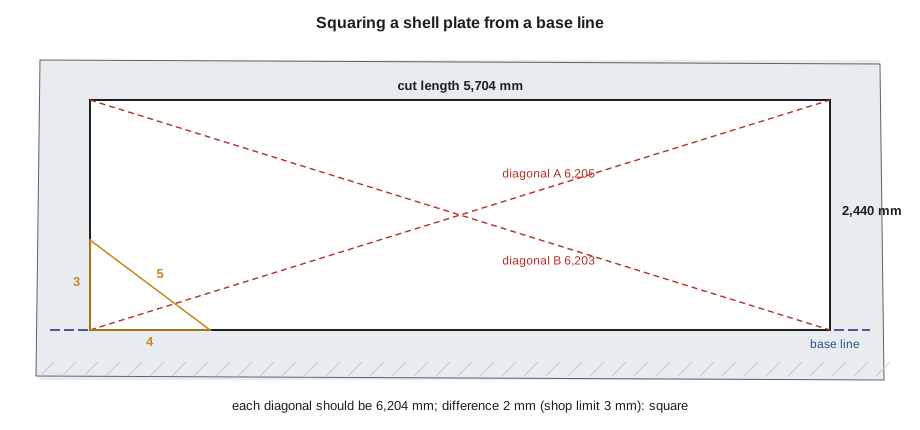
The diagonal check is the most important single check in plate layout, because it catches the error that the eye cannot see. A rectangle whose corners are out of square by a fraction of a degree looks perfect, but on a plate several metres long the error at the far end is many millimetres, and on a rolled shell it shows up as a long seam that does not close evenly, wider at one end than the other.
For the V-412 shell course 2 plate, Kiera lays out the rectangle 5,704 mm long and 2,440 mm wide. The diagonals should each be 6,204 mm; she measures 6,205 mm and 6,203 mm. The shop's tolerance for diagonal difference on shell plates is 3 mm, so the plate is square enough to cut.
Plate direction and identification
Plate has a rolling direction, the direction it was rolled at the mill, and its strength and toughness can differ slightly along and across it. Some specifications require that shell plates be rolled into shells with the rolling direction around the circumference, and the mill's marks show which way it runs. The layout must also place the heat number and piece mark where they will survive cutting, rolling and welding, usually on the outside of the shell near a corner, and transfer them to any offcut that will be used. On V-412, Harjit witnesses the transfer and initials the cut sheet before Kiera's rectangle goes to the burning table.
Cutting allowances and the kerf
Every cutting process removes some metal. The width of the cut, called the kerf, is a couple of millimetres for plasma on thin plate and more for oxyfuel on thick plate. The layout line marks the edge of the finished piece, and the cut is made on the scrap side of the line, so that the line just shows on the piece after cutting. If the cut is made on the line, half the kerf comes off the piece. On CNC burning tables, the machine offsets the torch path by half the kerf automatically, but the operator must set the kerf correctly for the process and thickness. Where a cut edge will be bevelled or machined later, the cut list adds a machining allowance.
Laying out bevels
Bevels on shell plates prepare the long and circumferential seams for welding. The welding symbol on the drawing, as lesson 3 showed, gives the groove angle, the root face and the root opening; the welding procedure gives the tolerance on each. For a single-V groove with a 60-degree included angle, each plate edge is bevelled at 30 degrees, leaving a root face, a small flat at the root that keeps the bevel from burning through. The width of the bevel on the plate surface, measured back from the edge, is the plate thickness less the root face, multiplied by the tangent of the bevel angle.
Layout marks the bevel by a line on the plate surface at this distance from the cut line, so that the bevelling machine or the torch operator can check it, and writes the bevel angle, the side and the root face along the edge. On a shell plate, the side matters: the drawing may call for the bevel on the outside, the inside, or both, and the plate will be rolled after bevelling, so the layout hand must know which face will be the outside of the shell. Joanne's rule is to mark the outside face OUT in large letters before anything else is done.
Hole patterns and the bolt circle
Holes in plate are laid out by their centres, either from the reference lines as coordinates or, for circular patterns, on a bolt circle. On the V-412 base ring, eight anchor bolt holes lie on a bolt circle of 2,100 mm diameter. By convention, bolt holes straddle the centre lines: no hole falls on a centre line, and the first hole is half a space off it. This places the holes symmetrically about both centre lines, so the vessel can be turned on its foundation in either direction without the holes changing position. Nozzle flanges follow the same rule, so that flanges bolt up with the bolts straddling the vessel's centre lines.
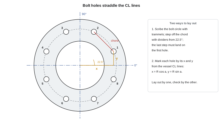
There are two ways to lay out the holes. With the bolt circle scribed by trammels from the centre, the holes are stepped off with dividers set to the chord, starting half a space off a centre line; the last step should land on the starting point. Or each hole is located by its coordinates from the centre, measured along and square to the centre lines. The coordinates method suits CNC cutting and is easier to check; the dividers method is faster by hand. On a large ring, Joanne uses both: coordinates to mark, and the chord to check.
Kiera's script for the course 2 plate and base ring checks the diagonals, gives the coordinates of the eight anchor bolt holes, and works out the bevel width for the long seams.
# Plate layout checks: diagonals, bolt holes and bevel (metric)
from math import sqrt, cos, sin, tan, radians, gcd
MODE = "mm"

def frac(x, den=16):
    sign = "-" if x < 0 else ""
    n = round(abs(x) * den); whole, rem = divmod(n, den)
    if rem == 0:
        return f"{sign}{whole} in"
    g = gcd(rem, den)
    return f"{sign}{whole} {rem // g}/{den // g} in" if whole else f"{sign}{rem // g}/{den // g} in"

def show(x):
    return f"{x:,.1f} mm" if MODE == "mm" else f"{x:.3f} in ({frac(x)})"

# 1. squaring the shell plate
L, W = 5_704, 2_440
d = sqrt(L * L + W * W)
print("plate", show(L), "by", show(W), "-> each diagonal should be", show(d))
d1, d2 = 6_205, 6_203
tol = 3
print("measured diagonals", show(d1), "and", show(d2), "difference", show(abs(d1 - d2)),
      "OK" if abs(d1 - d2) <= tol else "RE-SQUARE")

# 2. anchor bolt holes on the base ring, straddling the centre lines
R, n = 1_050, 8
print(f"\n{n} holes on a {show(2 * R)} bolt circle (x east, y north from the vessel centre)")
for k in range(n):
    a = radians(360 / n * k + 180 / n)          # half a space off the centre line
    print(f"hole {k + 1}: x {show(R * cos(a)):>22}  y {show(R * sin(a)):>22}")

# 3. bevel on a single-V long seam
t, face, ang = 16, 2, 30.0                    # plate, root face, bevel angle (degrees)
print("\nbevel width on the plate surface:", show((t - face) * tan(radians(ang))))plate 5,704.0 mm by 2,440.0 mm -> each diagonal should be 6,204.0 mm measured diagonals 6,205.0 mm and 6,203.0 mm difference 2.0 mm OK 8 holes on a 2,100.0 mm bolt circle (x east, y north from the vessel centre) hole 1: x 970.1 mm y 401.8 mm hole 2: x 401.8 mm y 970.1 mm hole 3: x -401.8 mm y 970.1 mm hole 4: x -970.1 mm y 401.8 mm hole 5: x -970.1 mm y -401.8 mm hole 6: x -401.8 mm y -970.1 mm hole 7: x 401.8 mm y -970.1 mm hole 8: x 970.1 mm y -401.8 mm bevel width on the plate surface: 8.1 mm
Every hole is 970.1 mm one way and 401.8 mm the other from the centre, in some combination of signs, which is a quick check that the pattern is symmetrical. The bevel on the 16 mm plate, with a 2 mm root face at 30 degrees, is 8.1 mm wide on the surface.
Marking a plate for the next trade
When Kiera's layout is done, the plate carries everything the burner, the bevelling machine operator, the roll operator and the fitter will need: cut lines with the scrap side crossed, the bevel lines and notes on each edge, the OUT face marked, the heat number and piece mark, the roll direction, and reference lines for fitting, such as the quarter lines that will mark 0, 90, 180 and 270 degrees once the plate is rolled. Every reference line is set back a fixed distance from the edges, so that it survives bevelling and welding; the set-back is written on the plate. Joanne checks the layout before it goes to the burning table and initials the cut sheet.
Worked problem
Bevel width
A 20 mm plate is to be bevelled at 37.5° with a 2 mm root face. How wide is the bevel on the plate surface?
Show solution
- Depth of bevel: 20 − 2 = 18 mm.
- Tangent of 37.5°: 0.767.
- Width: 18 × 0.767 = 13.8 mm.
Answer: About 13.8 mm.
Nesting the small parts
A shell plate leaves offcuts, and the small parts of a vessel are cut from them: reinforcing pads, clips, lifting lug doublers, gussets and the nameplate bracket. Each part must carry the heat number of the plate it came from, and on pressure parts the material must match the bill of material. Joanne nests these parts on the offcuts at the same time as the main layout, so that the identification is transferred once, under Harjit's eye, and so that pieces with a required rolling direction are oriented correctly. A circular part such as a reinforcing pad is laid out by scribing its outside and its opening with trammels from a punched centre, and the centre punch mark is kept so that the opening can be checked against the nozzle neck later.
Small parts are where layout errors hide, because nobody checks a clip as carefully as a shell plate. Joanne's rule is that every part is measured after cutting against its drawing, whatever its size, and every part is marked before it leaves the cutting area.
Common mistakes
MistakeMeasuring from the mill edge.
InsteadEstablish a base line inside the edge and measure everything from it.
MistakeCutting on the line.
InsteadCut on the scrap side so the line just shows on the piece.
MistakeSkipping the diagonal check because the corners look square.
InsteadMeasure both diagonals before every cut.
MistakePutting a bolt hole on a centre line.
InsteadStraddle the centre lines with the first hole half a space off.
MistakeBevelling the wrong face of a plate that will be rolled.
InsteadMark the outside face first and bevel to the drawing.
Summary and key terms
- Mill edges are not references; lay out from a base line set in from the edge.
- Square the plate with a 3-4-5 triangle or a large square and check it by its diagonals.
- Cut on the scrap side of the line and allow for the kerf.
- Bevel width on the surface is the thickness less the root face, times the tangent of the bevel angle.
- Bolt holes straddle the centre lines; lay them out by chord or by coordinates and check one with the other.
- Mark the outside face, identification, roll direction and set-back reference lines before the plate leaves layout.
- Base line
- A straight reference line set in from a plate edge, from which layout is measured.
- Kerf
- The width of metal removed by a cut.
- Root face
- The flat at the root of a bevel that keeps the edge from burning through.
- Bolt circle
- The circle through the centres of a ring of bolt holes.
- Straddling the centre lines
- Placing bolt holes so no hole falls on a centre line.
- Camber
- A curve along the length of a plate as it comes from the mill.
Practice problems
Work each problem on paper first, then reveal the answer to check.
A plate is 3,000 × 1,500 mm. What should each diagonal be?
Show answer
√(3,000² + 1,500²) = 3,354 mm.
Four holes on a 600 mm bolt circle straddle the centre lines. What are the coordinates of the first?
Show answer
300 cos 45° = 212.1 mm each way.
Why is the cut made on the scrap side of the line?
Show answer
So the kerf comes off the scrap and the piece keeps its size.
What is the bevel width on 12 mm plate with a 2 mm root face at 30 degrees?
Show answer
10 × 0.577 = 5.8 mm.
Lesson quiz · 5 questions
Score 60% or more to complete this lesson.
Create a free account to save your progress, take quizzes and earn a certificate.