
BLR-130 · Lesson 2 of 12 · 19 min
Reading fabrication and shop drawings
A fabrication drawing is a contract between the engineer who designed the piece and the people who build it. Everything the shop needs to know should be on it or in a document it references: the shape and size of every part, the material, the welds, the tolerances, the inspection and the finish. A layout hand reads a drawing more closely than almost anyone else, because every number on it is about to become a line on steel. This lesson covers the kinds of drawings a boilermaker meets, how they are arranged, how dimensions are given and why the way they are given matters, and the habits that catch errors before the steel is cut.
Kinds of drawings
On the V-412 job, the drawing package that reaches the shop has several layers. The general arrangement drawing shows the whole vessel: its overall dimensions, the orientation of every nozzle, the supports, and the design data block with the pressure, temperature, material and code. Detail drawings show individual parts such as nozzles, the skirt, the base ring and internal parts, with enough dimensions to make them. Shop drawings, prepared by Ironbridge's own detailer from the engineer's drawings, show how the shop will build each piece: the plate layout, the seam locations, the bevels and the weld sequence. A nozzle schedule lists every opening by its mark, size, rating, projection and orientation. And the bill of material lists every part with its mark, quantity, material specification and size.
Field work brings other drawings. A boiler outage comes with the boiler maker's original arrangement drawings, often decades old, marked up with repair details. A tank repair comes with a shell plate layout showing which plates are replaced. Structural steel comes with erection drawings, which show where each piece goes, and shop detail drawings, which show how each piece is made.
| Drawing | What a layout hand takes from it |
|---|---|
| General arrangement | Overall dimensions, nozzle orientation, design data, the datum lines everything is measured from |
| Detail drawing | Part sizes, hole patterns, bevels and welds for each piece |
| Shop drawing | Plate layout, seam positions, cut sizes with allowances, weld sequence |
| Nozzle schedule | Mark, size, rating, projection and orientation of each opening |
| Bill of material | Mark, quantity, material specification and size of every part |
| Erection drawing | Where each structural piece goes and its mark |
Views and projection
Most fabrication drawings use orthographic projection: the object is shown in separate views, each looking straight at one side. The front view, or elevation, shows height and width; the top view, or plan, shows width and depth; the side view shows height and depth. Views line up with each other on the sheet, so a feature in the front view lines up vertically with the same feature in the plan and horizontally with the same feature in the side view. North American drawings use third-angle projection, in which the plan sits above the elevation and the right side view sits to the right of it. Some drawings from overseas suppliers use first-angle projection, with the views swapped; the projection symbol in the title block tells which.
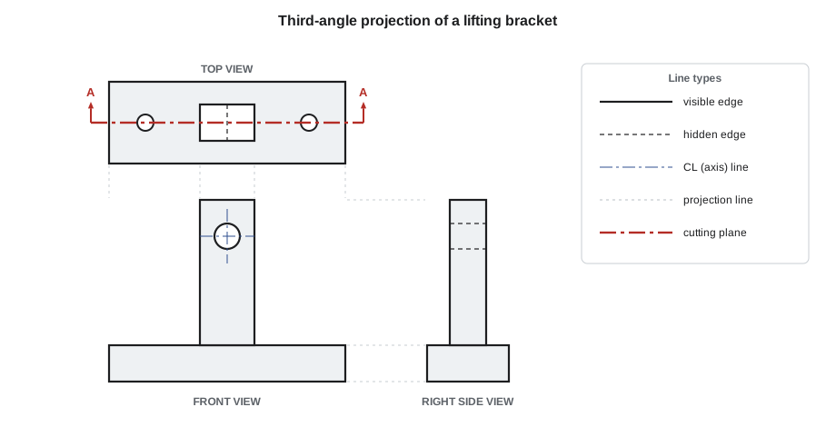
Line types carry meaning. Solid thick lines are visible edges; dashed lines are hidden edges; long-and-short dashed lines are centre lines; thin lines with arrows are dimension and extension lines; and heavy lines with arrows at the ends mark a cutting plane, where a section view shows the object as if sliced through. Section views are common on vessel drawings for nozzles, flanges and supports, because they show wall thickness and weld preparations that the outside views hide.
Vessel drawings add their own conventions. The vessel's orientation is shown in a plan view with the nozzles at their angles around the shell, measured from a reference direction, usually plant north or 0 degrees. Elevations along the vessel are given from datum lines: the bottom tangent line, where the bottom head's curve meets the straight shell, is the usual datum for a vertical vessel; the base of the skirt is the datum for the support. Every nozzle has an orientation angle and an elevation, and the layout hand marks both on the rolled shell.
Scale and the title block
Drawings are rarely full size. A general arrangement of V-412 might be drawn at 1:20, so 1 unit on the paper is 20 on the vessel; a detail might be at 1:5 or 1:2. The scale is in the title block, along with the drawing number, revision, title, who drew and checked it, the date, the projection symbol and the general tolerances that apply where a dimension has none of its own. The rule in every shop is the same: never scale a drawing. Measure from the drawing only to understand proportions, never to get a dimension. If a dimension is missing, ask for it. Prints shrink and stretch, and a drawing printed on a smaller sheet is no longer at its stated scale.
The revision block matters as much as the title block. Drawings change as a job goes on, and each change is recorded with a letter or number, a description and a date. Before layout starts, Joanne checks that the drawing on her table carries the latest revision on the shop's document register. Kiera learns why on her second day, when a nozzle elevation she was about to mark has been changed in revision 2, issued that morning.
How dimensions are given
A dimension tells the size of a feature or its location from something else. There are two common ways to give locations along a line. Chain dimensions give each space from the previous feature: 450 mm (18 in) to the first nozzle, then 1,350 mm (54 in) to the next, and so on. Running dimensions, also called baseline or ordinate dimensions, give every feature's distance from one datum: 450, 1,800 and 3,400 mm. The two say the same thing on paper, but they behave very differently when the steel is marked.
When a layout hand marks chain dimensions by measuring each space from the last mark, any small error in each measurement carries forward. The last feature can be out by the sum of every error before it. When the hand marks every feature from the datum with one tape pull, each mark carries only its own error. Good layout practice marks from the datum, whatever way the drawing is dimensioned, and uses the chain dimensions only as a check.
Joanne has Kiera compare the two ways for the V-412 nozzle elevations, measured from the bottom tangent line, assuming each tape reading could be off by up to 1.5 mm.
# Running versus chain dimensions for nozzle locations on the V-412 shell (metric)
MODE = "mm"
chain = [450, 1_350, 1_600, 900, 1_800, 1_220]       # spaces between features along the shell, from the bottom tangent line
names = ["N1 outlet", "N2 inlet", "M1 manway", "N3 level", "N4 level", "top tangent line"]
err = 1.5           # possible error in marking out each measurement (+ or -)

def show(x):
    if MODE == "mm":
        return f"{x:,.1f} mm"
    return f"{x:,.3f} in"

pos = 0
print("feature            running dim   worst error if chained   worst error if running")
for i, (n, c) in enumerate(zip(names, chain), 1):
    pos += c
    print(f"{n:<18} {show(pos):>12}   {show(i * err):>22}   {show(err):>22}")
print("overall length from the chain:", show(sum(chain)))feature running dim worst error if chained worst error if running N1 outlet 450.0 mm 1.5 mm 1.5 mm N2 inlet 1,800.0 mm 3.0 mm 1.5 mm M1 manway 3,400.0 mm 4.5 mm 1.5 mm N3 level 4,300.0 mm 6.0 mm 1.5 mm N4 level 6,100.0 mm 7.5 mm 1.5 mm top tangent line 7,320.0 mm 9.0 mm 1.5 mm overall length from the chain: 7,320.0 mm
Chained, the last mark at the top tangent line could be out by 9 mm; marked from the datum, every mark stays within 1.5 mm. On a vessel where nozzle elevations must be within a few millimetres, that difference decides whether the piping fits in the field.
Tolerances on drawings
No dimension can be made exactly. A tolerance states how far a finished dimension may differ from the drawing. It may be written beside the dimension, as plus-or-minus a value, or it may come from the general tolerance note in the title block, or from the code or specification the vessel is built to. Vessel codes set tolerances on things like the roundness of a shell and the alignment of plates at a seam; the purchaser's specification may add tighter ones, such as the location of nozzles or the straightness of the shell. Lesson 11 covers these tolerances and how they are checked; for now, the point is that a layout hand must know which tolerance applies to every mark, because it decides how carefully the mark must be made and which method to use.
Notes, specifications and design data
Much of what a drawing says is in its notes. On V-412, the notes give the material specification for each part, the welding procedure for each seam, the radiography required, the post-weld heat treatment if any, the hydrostatic test pressure, the surface preparation and paint, and the shipping and nameplate instructions. The design data block gives the code, the design pressure and temperature, the corrosion allowance, the joint efficiency and the registration details. On the Canadian side, the design is registered with ABSA, Alberta's pressure equipment safety authority, which issues a Canadian registration number for it; on the American side, the vessel will carry the code stamp and be registered with the National Board. The layout hand does not design anything from this data, but the corrosion allowance and the material affect thicknesses and cut sizes, and the radiography and weld notes decide where seams can go.
The specification sometimes says something the drawing does not show. A purchaser may require that no seam pass behind a nozzle or a support clip, or that long seams in adjacent courses be offset by a set distance, or that the shell be built with its long seams in particular quadrants so they can be inspected later. Joanne keeps a short list of these requirements beside each job's drawings and checks the shop drawing against it before the first mark is made.
Habits that catch errors
Errors on drawings are not rare, and they are much cheaper to catch on paper. Experienced layout hands have a routine. They check that the dimensions add up: chains should sum to the overall dimension. They check that views agree: a nozzle shown at 90 degrees in the plan should not be on the wrong side in the elevation. They check that parts fit: the base ring's bolt circle must clear the skirt, the nozzle's reinforcing pad must clear the seams. They check revisions. And they mark up their own print, ticking each dimension as it is laid out, so that nothing is missed and nothing is done twice.
When something does not add up, the layout hand raises it through the shop's query process, usually a written request for information to the engineer, before the steel is cut. On V-412, Kiera's check finds that the chain of nozzle elevations on one revision adds up to 5 mm less than the overall shell length, because one space was changed in the last revision and the overall was not. The query takes a day to answer, and the cut is held until it is.
Worked problem
Running dimensions from chains
A shell has four features above the datum, chained at 300, 1,200, 900 and 1,500 mm. What running dimensions should be marked?
Show solution
- First feature: 300 mm.
- Second: 300 + 1,200 = 1,500 mm.
- Third: 1,500 + 900 = 2,400 mm.
- Fourth: 2,400 + 1,500 = 3,900 mm.
Answer: Mark 300, 1,500, 2,400 and 3,900 mm from the datum with one tape pull.
Marking up a working print
Joanne keeps the shop's master drawings clean and gives each layout hand a working print to mark up. As each dimension is laid out, it is ticked in one colour; as it is checked, in another. Questions are circled and numbered, and the number goes on the request for information. When the job is done, the working print shows exactly what was marked, what was checked and what was queried, and it is kept with the job records. Kiera's first working print for V-412 has fourteen ticks, fourteen checks and one circled question, the elevation chain that did not add up.
Common mistakes
MistakeScaling a dimension off the print.
InsteadNever scale a drawing; ask for any dimension that is missing.
MistakeLaying out from an old revision.
InsteadCheck the revision against the document register before marking.
MistakeMarking chain dimensions one from the next.
InsteadMark every feature from the datum and use the chains as a check.
MistakeReading a first-angle drawing as if it were third-angle.
InsteadCheck the projection symbol in the title block.
MistakeIgnoring the notes and specification.
InsteadRead the notes for seam, weld and inspection requirements before laying out.
Summary and key terms
- A drawing package has general arrangement, detail and shop drawings, a nozzle schedule and a bill of material.
- North American drawings use third-angle projection; line types show visible, hidden and centre lines and cutting planes.
- Vessel elevations are measured from datum lines such as the bottom tangent line; nozzles also have orientation angles.
- Never scale a drawing, and always check the revision.
- Mark locations from the datum; chain marking adds up errors.
- Notes and specifications carry seam, weld, inspection and registration requirements the views do not show.
- Orthographic projection
- Drawing an object in separate views, each looking straight at one side.
- Third-angle projection
- The North American arrangement, with the plan above the elevation.
- Tangent line
- The line where a head's curve meets the straight shell; a common datum.
- Chain dimension
- A dimension from one feature to the next.
- Running dimension
- A dimension from a single datum to each feature.
- Revision
- A recorded change to a drawing, identified by a letter or number.
Practice problems
Work each problem on paper first, then reveal the answer to check.
Chains of 250, 750 and 1,000 mm from a datum. What running dimensions are marked?
Show answer
250, 1,000 and 2,000 mm.
Why should a drawing never be scaled?
Show answer
Prints are not reliably at scale; dimensions must be given, not measured.
Where is the plan in third-angle projection?
Show answer
Above the front view.
What is the usual elevation datum for a vertical vessel?
Show answer
The bottom tangent line.
Lesson quiz · 5 questions
Score 60% or more to complete this lesson.
Create a free account to save your progress, take quizzes and earn a certificate.