
ARCH-210 · Lesson 6 of 12 · 21 min
Drawings from the model
Two weeks before midterm review, the studio is full of people staring at plans that look almost right. Joon-ho's plan shows the boathouse windows as thin lines with no sills, his section cuts through the roof but shows nothing beyond it, and every wall is drawn with the same heavy line. 'The model is good,' Professor Ferreira tells him. 'The drawing is not. In BIM, the drawing is a view of the model, and a view has settings: where it cuts, how far it looks, what it shows, how thick the lines are and what is written on it. The model holds the building. The view decides how you tell the story.'
Views are windows into the model
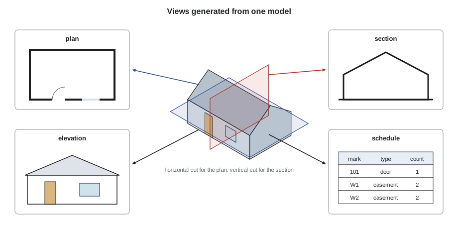
In a BIM program, every drawing begins as a view: a plan, ceiling plan, section, elevation, detail, 3D view, schedule or legend. Each view has a type, a scale, a level of detail, visibility settings for each category, and a crop region that limits what it shows. Views are live: the elements you see are the model's elements, so when the model changes, every view updates. Annotations such as dimensions, tags and text are placed in a view and belong only to that view, although tags read their information from the model.
Plans: the cut plane and the view range
A floor plan is a horizontal section. The program cuts the model at a set height above the level, the cut plane, typically 1.2 m (4 ft), and looks down. Elements that the cut plane passes through are drawn as cut, with heavier lines and cut patterns; elements below the cut, such as a floor finish, a counter top or a step, are drawn in projection with lighter lines; elements above the cut, such as upper cabinets or a beam, are normally hidden or shown dashed. The view range sets the top and bottom of what the plan sees. The script below sorts some boathouse elements the way a plan view does.
# How a plan view sorts elements: cut, seen below, or above the view range (m).
level = 0.0
cut = 1.2        # cut plane height above the level
bottom = 0.0       # bottom of the view range
top = 2.4        # top of the primary range
elements = {"exterior wall": (0.0, 2.4), "window": (0.9, 2.1), "bench": (0.0, 0.45), "work counter": (0.0, 0.9), "upper shelf": (1.5, 1.8), "roof beam": (2.4, 2.7)} # name: (bottom z, top z)
for name, (z0, z1) in elements.items():
    if z0 <= cut <= z1:
        how = "cut: drawn with heavy lines and the cut pattern"
    elif z1 < cut and z1 >= bottom:
        how = "below cut: drawn in projection with lighter lines"
    elif z0 > cut and z0 <= top:
        how = "above cut: hidden, or dashed if the view shows overhead items"
    else:
        how = "outside the view range: not shown"
print(f"{name:18s} {z0:5.2f} to {z1:5.2f} {how}")exterior wall 0.00 to 2.40 cut: drawn with heavy lines and the cut pattern window 0.90 to 2.10 cut: drawn with heavy lines and the cut pattern bench 0.00 to 0.45 below cut: drawn in projection with lighter lines work counter 0.00 to 0.90 below cut: drawn in projection with lighter lines upper shelf 1.50 to 1.80 above cut: hidden, or dashed if the view shows overhead items roof beam 2.40 to 2.70 above cut: hidden, or dashed if the view shows overhead items
Windows whose sills sit above the cut plane will not appear as openings at all, which is why clerestory windows often need a special plan region with a higher cut, or a symbolic representation in the window family. Stairs are cut at the cut plane, with the part above shown dashed and a break line, which the stair tool handles automatically. Reflected ceiling plans look up at the ceiling from below and show lights, diffusers and ceiling grids.
Sections, elevations and details
A section view is defined by a section line drawn in a plan, with a direction and a far clip depth that limits how far beyond the cut it looks. Elements cut are drawn heavy; elements beyond the cut are drawn in projection, often with lighter lines as they recede. Elevations are similar, but from outside the building with no cut. The section line in the plan and the section head that refers to its sheet and number are created automatically and stay correct when the section is moved to another sheet.
Callouts create enlarged views of part of another view, such as a wall section or a stair, at a larger scale and finer detail. At large scales, the model is rarely complete enough to show everything, and it should not be: modelling every flashing, sealant joint and fastener would make the model enormous. Instead, offices add 2D detail components, such as flashing profiles, blocking and sealant, and detail lines on top of the model geometry in the detail view, or draw standard details entirely in 2D in drafting views. The principle is to model what is coordinated and quantified, and draft what is only needed for explanation.
Graphics: line weights, patterns and templates
Drawings communicate through graphics. BIM programs assign line weights by category and by whether an element is cut or in projection, scaled automatically with the view scale, so that a wall cut in a 1:100 (1/8 in = 1 ft) plan has a heavier outline than a furniture outline seen below. Cut patterns show materials in section: concrete stipple, insulation batt pattern, earth hatch. Visibility and graphics overrides change how a category or a single element appears in one view, for example showing existing construction in halftone in a renovation plan or highlighting fire-rated walls in a life-safety plan.
View templates bundle these settings, scale, detail level, visibility of categories, overrides, filters and view range, so that every plan of a given kind looks the same. Offices maintain templates for design plans, construction plans, reflected ceiling plans, life-safety plans, sections and details. Applying a template is faster and more reliable than adjusting each view by hand, and when the office standard changes, updating the template updates every view that uses it. Filters add rules, such as showing every wall with a fire rating of one hour in red hatch, so drawings can display data visually.
BIM drawings have a reputation for looking mechanical: uniform lines, too much information, no sense of what matters. The cure is not to abandon the model but to design the graphics: set a clear hierarchy of line weights, hide what does not help the drawing's purpose, use halftone for context, and add hand-drawn emphasis where it helps. A plan for a client presentation and a plan for the framer are different drawings of the same model.
Annotation
Annotation turns views into construction documents. Dimensions attach to model elements, so they update when walls move; they can reference wall faces, core faces or centre lines, and offices set rules about which to use. Tags are annotation objects that read and display element data: a door tag shows the door's mark, a room tag its name and area, a wall tag its type. Because tags read the model, they cannot disagree with it; if a door's mark changes, its tag changes. Keynotes link drawing notes to a keynote file, often organized by MasterFormat, so that the same note text and number appear wherever the same material or assembly is noted. Text notes, symbols, revision clouds and matchlines complete the annotation set.
Sheets and the drawing set
Views are placed on sheets, which carry title blocks with the project name, the firm, the sheet number and title, the issue and revision history, and stamps. A view can appear on only one sheet, so that every cross-reference is unique: the section head in a plan reads, for example, section 3 on sheet A-301, and that reference updates if the section is moved. Sheet lists, drawing indexes and view lists are schedules of the sheets themselves, generated automatically.
Sheet numbering follows a system. Many Canadian offices follow conventions similar to the United States National CAD Standard, with a discipline letter and a number: A for architecture, S for structure, M for mechanical, and so on, followed by a sheet type digit, 1 for plans, 2 for elevations, 3 for sections, 5 for details, 6 for schedules, and a sequence number. The script checks a sheet list for the pattern and for duplicates.
# Check a sheet list: discipline letter, sheet type digit, sequence, and no duplicates
import re
sheets = ["A-001", "A-101", "A-201", "A-202", "A-301", "A-501", "A-601", "A-201", "S-101", "A-10"]
types = {"0": "general", "1": "plans", "2": "elevations", "3": "sections",
         "4": "large-scale views", "5": "details", "6": "schedules and diagrams"}
seen = set()
for s in sheets:
    m = re.fullmatch(r"([A-Z])-(\d)(\d\d)", s)
    if not m:
        print(f"{s:6s} does not follow the pattern X-###")
    elif s in seen:
        print(f"{s:6s} duplicate number")
    else:
        seen.add(s)
print(f"{s:6s} discipline {m.group(1)}, {types[m.group(2)]}, sheet {int(m.group(3))}")A-001 discipline A, general, sheet 1 A-101 discipline A, plans, sheet 1 A-201 discipline A, elevations, sheet 1 A-202 discipline A, elevations, sheet 2 A-301 discipline A, sections, sheet 1 A-501 discipline A, details, sheet 1 A-601 discipline A, schedules and diagrams, sheet 1 A-201 duplicate number S-101 discipline S, plans, sheet 1 A-10 does not follow the pattern X-###
Revisions are tracked in the model: each revision has a number, date and description, revision clouds are drawn around changes in views, and the sheets that contain clouded changes list the revision in their title block automatically. Before issuing, the team exports the sheets to PDF, and often to DWG for consultants who need 2D files, using export settings that map categories to layers and line weights consistently.
What the model cannot draw
Some information belongs on drawings but not in the model. Construction sequences, temporary works, typical details that apply everywhere, notes on intent, and diagrams that explain how a system works are better drawn or written. Some geometry is too small or too repetitive to model: nails, sealant beads, the individual courses of a brick wall. And some views, such as a perspective that explains the design to a client, may combine model output with rendering and hand work. The skill is deciding where the line falls: model what needs to be coordinated, counted or analysed; draw what needs only to be explained.
Worked problem
A wall section from the boathouse model
Wren needs a 1:20 (1 in = 1 ft-0 in) wall section through the warming hut from the footing to the ridge, showing every layer, the window head and sill, and the eave. Which parts come from the model and which must she add?
Show solution
- Create a callout from the building section at the exterior wall and set its scale and detail level to fine.
- From the model: the footing, floor assembly, wall layers, window frame, roof layers, fascia and gutter, all cut with their materials and patterns.
- Add 2D detail components: flashing at the window head and sill, the sill pan, sealant joints, the eave membrane, blocking and the drip edge.
- Annotate with keynotes linked to the specification sections, dimensions to the face of sheathing, and tags for the window and wall type.
Answer: The model supplies the coordinated assemblies; the detail view adds the small parts and explanation that only a construction drawing needs.
Exercise 6: a small drawing set
This exercise takes about six hours.
- Set up view templates for plans, sections and details with a clear line weight hierarchy.
- Produce a floor plan, a reflected ceiling plan, two elevations, a building section, a wall section callout and a door and window schedule from the boathouse model.
- Annotate with dimensions, tags and keynotes, and add 2D detail components only where the model does not show what is needed.
- Place the views on four sheets numbered to the office convention, and issue a revision with one clouded change.
- Deliverable: a PDF set of four sheets and a one-page note on which information came from the model and which was drafted.
Self-critique checklist
- Does every view use a template, and do similar views look the same?
- Is there a clear hierarchy of cut, projection and annotation line weights?
- Do section and callout references point to the correct sheets?
- Have I modelled what needs coordinating and drafted only what needs explaining?
Common mistakes
MistakeAdjusting each view by hand.
InsteadUse view templates so views are consistent and can be updated together.
MistakeExpecting the model to show every flashing and fastener.
InsteadAdd 2D detail components in detail views for small parts that are not coordinated.
MistakeDrawing dimensions and notes as unlinked lines and text.
InsteadUse model-linked dimensions, tags and keynotes so annotation updates with the model.
MistakeLeaving windows above the cut plane missing from plans.
InsteadAdjust the view range or plan region, or use symbolic lines in the family.
MistakeAccepting uniform, mechanical line weights.
InsteadDesign the graphics: hierarchy, halftone context and only what the drawing needs.
Summary and key terms
- Drawings in BIM are views of the model with their own scale, detail level, visibility and crop.
- A plan is a horizontal cut; the cut plane and view range decide what is drawn as cut, in projection or hidden.
- Sections, elevations and callouts are generated from the model; large-scale details add 2D components.
- View templates, line weights, patterns and filters make drawings consistent and readable.
- Dimensions, tags and keynotes read from the model, so annotation stays correct as the design changes.
- Sheets organize views into a numbered drawing set with automatic references and revisions.
- View
- A way of displaying the model, such as a plan, section or 3D view, with its own settings and annotation.
- Cut plane
- The height at which a plan view cuts the model.
- View range
- The top, cut plane, bottom and depth that define what a plan view shows.
- View template
- A saved set of view settings applied to many views.
- Tag
- An annotation that displays information read from a model element.
- Keynote
- A numbered note linked to a keynote file, usually organized by specification section.
- Callout
- An enlarged view of part of another view.
Practice problems
Work each problem on paper first, then reveal the answer to check.
A plan's cut plane is at 1.2 m (4 ft). Is a 0.9 m (3 ft) counter cut or seen in projection?
Show answer
Seen in projection below the cut, drawn with lighter lines.
Why can a view appear on only one sheet?
Show answer
So every reference to it, such as a section head, points to one unique sheet and number.
What does a door tag display, and where does the information come from?
Show answer
Usually the door mark; it reads it from the door element in the model.
Give two examples of information better drafted than modelled.
Show answer
Any two of: flashing and sealant in details, nails and fasteners, construction sequences, typical details, explanatory notes.
Decode sheet number A-301.
Show answer
Architecture, sections, sheet 1.
Lesson quiz · 5 questions
Score 60% or more to complete this lesson.
Create a free account to save your progress, take quizzes and earn a certificate.