
ARCH-210 · Lesson 5 of 12 · 21 min
Families and components
Ingrid spends a whole Saturday building a window. Not a real one: a parametric window family for the boathouse, with a frame, a sash, glass, a sill and a head trim, all of which stretch correctly when the width and height change. By the end of the day it flexes from a narrow slot to a wide picture window without breaking, and she is very proud of it. On Monday, Professor Ferreira opens the manufacturer's catalogue and shows that the real casement comes in eleven sizes, each with a different number of panes above a certain width. 'Your family is good,' she says. 'Now teach it the rule the manufacturer uses, and let it make the eleven types for you.'
Components in BIM
A building is assembled from components: doors, windows, plumbing fixtures, light fittings, furniture, casework, structural members, mechanical equipment. In BIM, each component is an object defined once and placed many times. Revit calls these definitions families; Archicad calls them library objects, written in its Geometric Description Language, GDL; Vectorworks uses symbols and plug-in objects. The ideas are the same in all of them: a component has geometry, parameters that control the geometry and carry data, and rules about how it is placed and displayed.
Components fall into three groups. System elements, such as walls, floors, roofs and ceilings, are built into the program and defined by types with layers, as you saw in lesson 4. Loadable components, such as doors, windows and furniture, are made in separate files and loaded into a project, so they can be shared between projects and downloaded from manufacturers. In-place or one-off elements are modelled directly in the project for a unique object, such as a sculptural reception desk. In-place elements are convenient but hard to reuse and easy to misuse; if an object appears more than once, it should be a proper component.
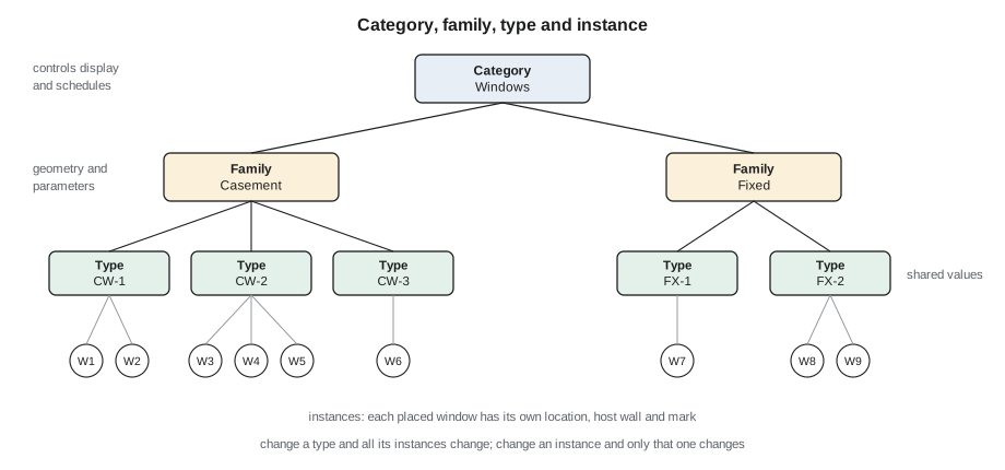
How a parametric component is built
A parametric component is built from reference planes or lines, geometry locked to them, and parameters that control the distance between them. In a window family, two vertical reference planes define the width and two horizontal ones the height; the frame, sash and glass are drawn and locked to those planes; and a width parameter controls the distance between the vertical planes. When the width changes, the planes move, and everything locked to them follows. Good families are built this way from the start: references first, then dimensions and parameters, then geometry locked to the references. Families in which geometry is simply drawn at one size and stretched later tend to break.
Parameters can be type or instance parameters, as for system elements. They can also be calculated from other parameters with formulas: the rough opening may be the width plus twice a shim allowance, the glass width may be the width minus the frames, and the number of panes may be the width divided by a maximum pane size, rounded up. Conditional formulas can switch parts on and off: a window wider than a certain size gains a mullion, a door taller than standard gains a transom. Visibility parameters let one family show a hardware set or a trim profile only when needed.
Families can contain other families, which is called nesting. A door family may nest a hardware family and a vision panel family; a curtain wall panel may nest a louvre. Nested families can be shared, so that the nested hardware appears in schedules on its own, or kept private to the parent. Nesting keeps families modular, but deep nesting makes them slow and hard to debug.
A component as a rule
The heart of a parametric component is a set of rules that turn a few inputs into consistent geometry and data. The script below describes the casement window family as a Python function. It takes a width and a height, calculates the number of panes from a maximum pane width, the glass size and area, and the rough opening, and then generates a type catalogue, the list of standard sizes a manufacturer offers.
# A window "family" as a function: parameters in, derived values out (m).
import math
def window(width, height, frame=0.06, max_pane=0.75, shim=0.01):
    panes = math.ceil((width - 2 * frame) / max_pane)          # number of vertical panes
    mull = panes - 1                                            # mullions between panes
    glass_w = (width - 2 * frame - mull * frame) / panes
    glass_h = height - 2 * frame
    return {"rough opening": (round(width + 2 * shim, 3), round(height + 2 * shim, 3)),
            "panes": panes, "pane glass": (round(glass_w, 3), round(glass_h, 3)),
            "glass area": round(panes * glass_w * glass_h, 3)}
# a table of types: each row is one window type
types = {"W0609": (0.6, 0.9), "W0912": (0.9, 1.2), "W1212": (1.2, 1.2), "W1815": (1.8, 1.5)}
for name, (w, h) in types.items():
    r = window(w, h)
    print(f"{name:6s} {w} x {h}: rough opening {r['rough opening']}, {r['panes']} pane(s) "
f"of {r['pane glass']}, glass area {r['glass area']} m2")W0609 0.6 x 0.9: rough opening (0.62, 0.92), 1 pane(s) of (0.48, 0.78), glass area 0.374 m2 W0912 0.9 x 1.2: rough opening (0.92, 1.22), 2 pane(s) of (0.36, 1.08), glass area 0.778 m2 W1212 1.2 x 1.2: rough opening (1.22, 1.22), 2 pane(s) of (0.51, 1.08), glass area 1.102 m2 W1815 1.8 x 1.5: rough opening (1.82, 1.52), 3 pane(s) of (0.52, 1.38), glass area 2.153 m2
This is exactly what a BIM family does internally. The program evaluates the formulas each time a parameter changes and redraws the geometry. A type catalogue, a simple text table of type names and parameter values, lets a project load only the sizes it needs instead of hundreds of types.
Level of detail and display
A component should display appropriately at every scale. At 1:200 (1/16 in = 1 ft) a door in plan is a simple opening with a swing; at 1:50 (1/4 in = 1 ft) it shows its frame; at 1:5 (3 in = 1 ft) a detail needs the actual frame profile. BIM programs handle this with detail levels, often called coarse, medium and fine, and with symbolic lines that appear only in plan or elevation. A good door family shows a simple swing arc in plan at every scale, because the 3D door leaf cut by the plan would look wrong, and shows the frame profile only at fine detail.
Components also carry materials for rendering and for takeoffs, and subcategories that let an office control how frames, glass and hardware are drawn in each view. Following the office's subcategory and material standards in every family is what keeps drawings consistent when families come from many sources.
Manufacturer content and libraries
Many manufacturers publish BIM components for their products, through their own websites or through platforms such as BIMobject, BIMsmith and the NBS National BIM Library. These save time and carry accurate data such as product codes, performance values and dimensions. They also vary in quality. Some are excessively detailed, modelling every screw, which makes a project slow; some use their own parameter names, so their data does not appear in office schedules; some are built at a single size and do not flex. Before loading downloaded content into a project, an office checks it: does it flex, is it in the right category, does it display correctly at each scale, how large is the file, and do its parameters map to the office's shared parameters?
Shared parameters solve the naming problem. A shared parameter is defined once, in a file of parameter definitions with unique identifiers, and then added to many families and projects. Because it has the same identity everywhere, it can appear in schedules and tags across all families that use it, and it exports to IFC consistently. Office libraries are built around a set of shared parameters, often aligned with classification systems and IFC property sets.
| Check | Why it matters |
|---|---|
| Category and subcategories | Controls display, schedules and IFC export class |
| Flexes correctly | Geometry must follow parameters without breaking |
| Detail levels and symbolic lines | Drawings must read correctly at every scale |
| File size and geometry | Over-detailed families slow the whole project |
| Parameter names | Must match office shared parameters to appear in schedules |
| Materials | Needed for rendering and quantity takeoffs |
| Insertion point and host | The component must place and align predictably |
Managing a component library
Offices keep a curated library of approved components, organized by category, with a naming convention for families and types and a person or team responsible for maintaining it. New components are tested before being added. Projects load from the library rather than from the internet directly, and project-specific components are reviewed at the end of a project and added to the library if they will be useful again. A disciplined library is one of the biggest productivity gains a BIM office can make; an undisciplined one, with five slightly different versions of the same door, is one of the biggest sources of errors.
Worked problem
A door that knows its fire rating
The warming hut connects to a small mechanical room through a door that must be fire-rated. Joon-ho needs the door schedule to show the rating, and he wants the door tag in plan to show a small rating symbol when a door is rated. How should he set up the door family?
Show solution
- Add a shared parameter called Fire Rating, defined as text, so that it appears in schedules and tags and exports to IFC.
- Decide whether it is a type or instance parameter. Because the rating depends on the wall the door sits in, he makes it an instance parameter.
- In the door tag family, add a label for the fire rating and set its visibility so that it shows only when the parameter has a value.
- Place the door, enter the rating, and check that it appears in the schedule, the tag and the IFC export under the standard property set.
Answer: A shared parameter, the right parameter kind and conditional visibility turn a piece of data into consistent information in schedules, tags and exports.
Exercise 5: a flexible window
This exercise takes about six hours.
- Build a casement window family from a window template: reference planes for width, height and sill, a frame and sash locked to them, glass and a sill profile.
- Add parameters for width, height, frame width and maximum pane width, and a formula for the number of panes.
- Add detail levels: a simple outline at coarse, the frame at medium and the profile at fine.
- Create a type catalogue of at least four sizes and load two of them into the boathouse model.
- Deliverable: the family file, a sheet showing it flexed to four sizes in plan, elevation and 3D, and a window schedule from the boathouse model.
Self-critique checklist
- Does the family flex from the smallest to the largest size without breaking?
- Is all geometry locked to reference planes rather than drawn at one size?
- Do the pane count and glass sizes follow the rule correctly at each size?
- Does the window display correctly at three scales?
Components beyond doors and windows
The same principles apply to every kind of component. Casework families carry door styles, hardware and countertop materials; plumbing fixture families carry connectors that the mechanical engineer's model can attach pipes to; light fitting families carry photometric data that rendering and lighting analysis can use; and furniture families carry the clearances they need around them, so that a room's layout can be checked for access. Structural framing families carry section properties that analysis software reads. In each case, the component is useful only if its geometry, parameters and data are built with the people who will use them in mind.
Archicad's library objects are written in GDL, a scripting language in which the geometry is generated by commands such as BLOCK, PRISM and REVOLVE, with parameters exposed in a settings dialog. Writing GDL is closer to programming than drawing, which makes complex, highly parametric objects possible but asks more of the author. In both approaches the lesson is the same: a component is a small program as much as a shape, and it should be tested like one, by flexing it through its full range, placing it in walls of different thicknesses, viewing it at every scale and scheduling it, before it goes into the office library.
Common mistakes
MistakeModelling a repeated object in place.
InsteadMake it a loadable component so it can be reused, scheduled and changed in one place.
MistakeDrawing family geometry at one size and stretching it afterwards.
InsteadBuild references and parameters first, then lock geometry to them.
MistakeLoading manufacturer content without checking it.
InsteadTest category, flexing, display, file size and parameter names before use.
MistakeCreating project parameters with ad hoc names in every family.
InsteadUse shared parameters so data appears consistently in schedules, tags and exports.
MistakeNesting families many levels deep.
InsteadKeep families modular but shallow, so they stay fast and debuggable.
Summary and key terms
- Components are defined once and placed many times; programs call them families, library objects or symbols.
- System elements, loadable components and in-place elements serve different purposes.
- Parametric components are built from references, parameters and geometry locked to the references.
- Formulas, conditional visibility and nesting turn a component into a set of rules.
- Detail levels and symbolic lines make components read correctly at every scale.
- Shared parameters and a curated library keep data consistent across a practice.
- Family
- In Revit, a definition of a component with geometry and parameters, from which types are made.
- GDL
- Geometric Description Language, the scripting language of Archicad library objects.
- Reference plane
- A non-printing plane in a family to which geometry is locked and dimensions are applied.
- Type catalogue
- A table listing the standard types of a family and their parameter values.
- Shared parameter
- A parameter defined once with a unique identifier and used across families and projects.
- Nested family
- A family placed inside another family.
Practice problems
Work each problem on paper first, then reveal the answer to check.
What is the difference between a system element and a loadable component?
Show answer
System elements, such as walls and floors, are built into the program and defined by types; loadable components are separate files loaded into projects.
Why lock geometry to reference planes?
Show answer
So that when parameters move the planes, the geometry follows predictably and the family flexes without breaking.
A casement is 1.8 m wide with 60 mm frames and a maximum pane width of 750 mm. How many panes does it need?
Show answer
(1.8 − 0.12) ÷ 0.75 = 2.24, rounded up to 3 panes.
Why do door families show a swing arc as symbolic lines in plan?
Show answer
Because the 3D leaf cut by the plan would not show the swing; symbolic lines give the conventional drawing.
Give two problems that downloaded manufacturer families can cause.
Show answer
Any two of: excessive detail and large files, wrong category, non-standard parameter names, failure to flex, poor display at some scales.
Lesson quiz · 5 questions
Score 60% or more to complete this lesson.
Create a free account to save your progress, take quizzes and earn a certificate.