
WLD-320 · Lesson 2 of 12 · 15 min
Pipe, fittings and schedules
Before Devon cuts a single bevel, Marta sends him to the pipe rack with a tape, a set of calipers and a list of six pieces to find. He comes back with five. The sixth, an NPS 3 schedule 80 pup, was in the rack, but he had measured its outside diameter, found it matched the NPS 3 schedule 40 next to it, and taken the wrong one. Marta uses the mistake to start the lesson: in pipe, the outside diameter stays the same for a given size, and the wall changes with the schedule. A welder who cannot read pipe sizes, schedules and fitting markings will fit the wrong pieces together, use the wrong procedure, or set up a joint that cannot be welded to the drawing.
Nominal pipe size
North American pipe is sized by nominal pipe size, or NPS, which is a number that names the size but is not a measurement. For NPS 1/8 to NPS 12, the nominal size is roughly the inside diameter of the old standard-weight pipe; the actual outside diameter is larger. NPS 2 pipe has an outside diameter of 2.375 in, NPS 6 is 6.625 in, and NPS 12 is 12.750 in. From NPS 14 up, the outside diameter equals the nominal size in inches: NPS 14 is 14 inches outside. Metric documents use DN, the nominal diameter, so NPS 2 is DN 50 and NPS 6 is DN 150, but the outside diameter is the same physical pipe.
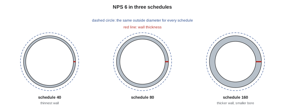
The key fact is that all pipe of one NPS has the same outside diameter, whatever its wall. That lets fittings, flanges, supports and clamps fit every pipe of that size, and it means that two pieces of the same size line up on the outside when they are fitted. The wall thickness, and therefore the inside diameter, changes with the schedule.
Schedules and wall thickness
The schedule number names the wall thickness for each size. Common carbon steel schedules are 40, 80 and 160, with 10, 20, 30, 60, 100, 120 and 140 used less often. A higher schedule means a thicker wall and a smaller inside diameter. The wall for a given schedule is different for each size: schedule 40 is 0.154 in on NPS 2 and 0.280 in on NPS 6. Older names are still used too: STD (standard), XS (extra strong) and XXS (double extra strong). STD is the same as schedule 40 up to NPS 10, and XS the same as schedule 80 up to NPS 8, but they differ at larger sizes. Stainless pipe uses the same outside diameters with its own schedule list, marked with an S, such as 10S and 40S.
Carbon steel pipe dimensions are set in ASME B36.10M, and stainless in ASME B36.19M. The table below gives a few sizes that Devon will meet on the Unit 4 spools.
| NPS | Outside diameter | Sch 40 wall | Sch 80 wall | Sch 160 wall |
|---|---|---|---|---|
| 1 | 1.315 in | 0.133 in | 0.179 in | 0.250 in |
| 2 | 2.375 in | 0.154 in | 0.218 in | 0.344 in |
| 3 | 3.500 in | 0.216 in | 0.300 in | 0.438 in |
| 4 | 4.500 in | 0.237 in | 0.337 in | 0.531 in |
| 6 | 6.625 in | 0.280 in | 0.432 in | 0.719 in |
| 8 | 8.625 in | 0.322 in | 0.500 in | 0.906 in |
Mill tolerance matters to the welder. Seamless pipe can have a wall up to 12.5 percent thinner than nominal and still meet its specification, and the wall may vary around the circumference. Two pieces of the same size and schedule can therefore have slightly different inside diameters, which shows up as misalignment at the root. Lesson 4 shows how fitters deal with it.
# Pipe size lookup: outside diameter, wall, inside diameter and mass per unit length
OD = {1: 1.315, 2: 2.375, 3: 3.5, 4: 4.5, 6: 6.625, 8: 8.625}
WALL = {'40': {1: 0.133, 2: 0.154, 3: 0.216, 4: 0.237, 6: 0.28, 8: 0.322},
        '80': {1: 0.179, 2: 0.218, 3: 0.3, 4: 0.337, 6: 0.432, 8: 0.5}}
K = 10.69     # steel mass factor: mass per length = K x (OD - t) x t
for nps, sch in [(2, '80'), (3, '40'), (3, '80'), (6, '40'), (6, '80')]:
    od, t = OD[nps], WALL[sch][nps]
    bore = od - 2 * t
    m = K * (od - t) * t
    print(f"NPS {nps} sch {sch}: OD {od} in, wall {t} in, ID {bore:.3f} in, {m:.1f} lb/ft")
t12 = WALL['80'][6] * 0.875
print(f"NPS 6 sch 80 minimum wall with 12.5 % mill tolerance: {t12:.3f} in")NPS 2 sch 80: OD 2.375 in, wall 0.218 in, ID 1.939 in, 5.0 lb/ft NPS 3 sch 40: OD 3.5 in, wall 0.216 in, ID 3.068 in, 7.6 lb/ft NPS 3 sch 80: OD 3.5 in, wall 0.3 in, ID 2.900 in, 10.3 lb/ft NPS 6 sch 40: OD 6.625 in, wall 0.28 in, ID 6.065 in, 19.0 lb/ft NPS 6 sch 80: OD 6.625 in, wall 0.432 in, ID 5.761 in, 28.6 lb/ft NPS 6 sch 80 minimum wall with 12.5 % mill tolerance: 0.378 in
Devon's mistake in the rack makes sense in the numbers. The NPS 3 schedule 40 and schedule 80 pieces have the same outside diameter; only the bore and the weight differ. Marta shows him the quicker check: look at the end, measure the wall with calipers, or read the stencil.
Reading pipe markings
Pipe is marked along its length by the mill with ink stencil or paint. A typical marking gives the manufacturer, the specification and grade, such as A106 Grade B, often with dual markings such as A53 and API 5L where the pipe meets more than one, the size and schedule or wall, the heat number, and sometimes the hydrostatic test pressure and the country of origin. The heat number is the identity of the batch of steel the pipe was made from, and it links the pipe to the mill test report, which lists the chemistry and mechanical properties.
On a code job the heat number must be kept on every piece. When a length is cut, the fitter transfers the heat number to each piece before it leaves the saw, so that the material can still be traced after the original stencil has been cut off. Lucia checks heat numbers against the material records when she inspects the spools, and a piece without a heat number is held until its identity is proven.
Fittings
Butt-weld fittings, made to ASME B16.9, change the direction or size of a line or add a branch, and have ends beveled to match the pipe. The common ones are elbows, tees, reducers and caps. Elbows come in 90 and 45 degree versions, and in long radius, where the center-to-face dimension is one and a half times the nominal size, and short radius, where it equals the nominal size. Tees are straight, with a branch the same size as the run, or reducing, with a smaller branch. Reducers are concentric, centered on the line, or eccentric, with one side flat so that a line can stay level along its top or bottom. Fittings are marked with the manufacturer, material, size, schedule and heat number, and their wall must match the pipe they are welded to.
Forged fittings to ASME B16.11 are used on small-bore lines, usually NPS 2 and smaller. They come as socket-weld fittings, where the pipe slides into a socket and is joined with a fillet weld, and threaded fittings. Lesson 10 covers socket welds. Branch connections can also be made with forged branch outlet fittings, often called by trade names, which are welded onto the run pipe over a hole cut in it.
| Fitting | Use | Welding note |
|---|---|---|
| Long-radius 90 elbow | Changes direction with low flow loss | Butt welds at both ends; heavy wall on the inside of the bend |
| Short-radius 90 elbow | Tight spaces | Less common; check the procedure covers it |
| Equal or reducing tee | Branches | Three butt welds |
| Concentric reducer | Changes size on the centerline | Two butt welds of different sizes |
| Eccentric reducer | Keeps the top or bottom of the line level | Mark the flat side before fitting |
| Weld neck flange | Bolted connection to equipment or valves | Butt weld to pipe; bolt holes must straddle the centerlines |
| Socket-weld fitting | Small-bore lines | Fillet weld with a gap at the bottom of the socket |
Flanges
Flanges join piping to valves, equipment and other piping with bolts, so the line can be taken apart. Most process flanges are made to ASME B16.5 up to NPS 24 and are rated in pressure classes: 150, 300, 600, 900, 1500 and 2500. A weld neck flange has a long tapered hub with a beveled end that is butt welded to the pipe, and it is the usual choice on process lines. A slip-on flange slides over the pipe and is fillet welded inside and out, and a socket-weld flange takes small-bore pipe in a socket. The bore of a weld neck flange must match the pipe's schedule, or the root will have a step that lesson 4 deals with.
When a flange is welded to a spool, its bolt holes must line up with the mating flange. The standard practice is that bolt holes straddle the principal centerlines, called two-holing: looking at the flange face, no hole sits on the vertical or horizontal centerline, but the holes on either side are equally spaced from it. A flange welded one hole out of position cannot be bolted to its mate, and the spool must be cut and rewelded. Raj marks the flange orientation on the iso, and Devon learns to check it with a flange level and pins before he tacks.
Material traceability
Every piece in a code spool, pipe, fitting and flange, must be traceable to its specification and heat. The welder's part is simple but important: keep the markings visible and transferred, do not weld a piece that has no marking, and record any material problem rather than fixing it quietly. A carbon steel elbow welded into a stainless line, or a schedule 40 fitting welded into a schedule 80 line, is a defect even if the weld is perfect, and it is often found only when the inspector checks the markings or a positive material identification test is run.
Checking pipe and fittings before fit-up
Before a piece goes to the fitting table, the fitter checks it. The ends must be square and free of damage, because a dented end or a gouge in the bevel will show up as a gap or a step at the root. The inside must be clean of mill scale, rust, dirt and anything else that could be welded into the root or carried down the line. Fittings are checked for the right size, schedule, material and heat number, and for the right type: a long-radius elbow and a short-radius elbow look alike on a shelf until they are measured. Pipe that has been stored outside may have water or ice inside it, and a cold piece brought into a warm shop sweats, which puts moisture on the bevel.
Devon also learns to check the ends of fittings against the pipe. A schedule 80 elbow fitted to schedule 80 pipe from a different mill can still show a small difference in bore, because each piece has its own tolerance. On the Unit 4 spools, Raj has marked the few joints where the drawing calls for a different wall on each side, such as a heavy-wall valve fitted to a lighter line, and those joints need a tapered transition that lesson 4 explains. Marta's rule is simple: measure both sides of every joint before you fit it, because it is cheaper to find the problem on the table than on the film.
Hartwell keeps a small reference board in the fitting area with short pieces of the common sizes and schedules cut in half, so that a new apprentice can see the difference between schedule 40 and schedule 80 at a glance and feel the weight of each. Devon spends ten minutes with it and never takes the wrong pup again.
Common mistakes
MistakeIdentifying pipe by its outside diameter alone.
InsteadCheck the wall or the stencil; all schedules of one size share the outside diameter.
MistakeCutting a length without transferring the heat number.
InsteadMark the heat number on every piece before it leaves the saw.
MistakeFitting a fitting of a different schedule from the pipe.
InsteadMatch the fitting wall to the pipe, or follow the procedure for unequal walls.
MistakeWelding a weld neck flange with a bolt hole on the centerline.
InsteadTwo-hole the flange and check it with a level before tacking.
MistakeUsing an eccentric reducer without marking the flat side.
InsteadMark the flat side and set it as the drawing shows.
Summary and key terms
- NPS names a size; the outside diameter is fixed for each size.
- The schedule sets the wall; higher schedules have thicker walls and smaller bores.
- Seamless pipe wall can be 12.5 percent under nominal.
- Markings give specification, grade, size, schedule and heat number.
- Butt-weld fittings follow ASME B16.9, flanges ASME B16.5, and socket fittings ASME B16.11.
- Every piece must stay traceable to its heat.
- NPS
- Nominal pipe size, a size name that fixes the outside diameter.
- Schedule
- A number that sets the wall thickness of pipe for each size.
- Heat number
- The identity of the batch of steel, linking pipe or fittings to the mill test report.
- Long-radius elbow
- An elbow whose center-to-face dimension is one and a half times the nominal size.
- Two-holing
- Setting flange bolt holes to straddle the vertical and horizontal centerlines.
Practice problems
Work each problem on paper first, then reveal the answer to check.
What is the inside diameter of NPS 4 schedule 80 pipe?
Show answer
4.500 - 2 x 0.337 = 3.826 in.
What is the minimum wall of NPS 2 schedule 80 pipe with 12.5 percent mill tolerance?
Show answer
0.218 x 0.875 = 0.191 in.
What is the center-to-face dimension of an NPS 6 long-radius 90 elbow?
Show answer
1.5 x 6 in = 9 in.
Lesson quiz · 5 questions
Score 60% or more to complete this lesson.
Create a free account to save your progress, take quizzes and earn a certificate.