
SMW-420 · Lesson 8 of 12 · 19 min
CNC plasma cutting
Every fitting on the Eastgate shop drawings has to become a flat pattern before it can be formed. In SMW-120 and SMW-210, Kai Ferreira laid out patterns by hand with parallel line, radial line and triangulation methods. In a modern shop those same patterns are calculated by fabrication software and cut by a computer numerically controlled, or CNC, plasma table. This lesson explains how Keelson's plasma table works, how parts are nested on a sheet, what the cutting data contains, how cut quality and speed are controlled, and how the table is run safely. Walt Szymanski, the shop foreman, has run plasma tables for twenty years, and he spent a week teaching Kai the machine during the Eastgate fabrication.
How plasma cutting works
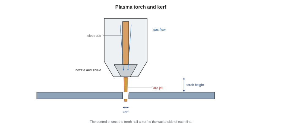
A plasma torch forces a gas, usually compressed air for thin galvanized sheet, through a small nozzle with an electric arc between an electrode inside the torch and the workpiece. The arc heats the gas until it becomes plasma, an electrically conducting gas hot enough to melt the metal, and the narrow, fast jet blows the molten metal out of the cut. Because the arc must pass to the workpiece, plasma cuts only conductive metals, which includes every sheet metal the shop uses: galvanized steel, stainless steel, aluminum and copper. On thin sheet, plasma cuts fast and cleanly, which is why it has largely replaced hand layout and nibbling for fittings.
The width of the cut is called the kerf. On thin galvanized sheet with a fine-cut torch, the kerf is typically a millimeter or two, or a few hundredths of an inch, depending on the amperage, the nozzle and the cutting speed. The CNC control compensates for the kerf by moving the torch half a kerf to the outside of an outline and to the inside of a hole, so that the finished part is the right size. Wrong kerf compensation is one of the commonest reasons for fittings that do not fit together: a 0.04 in error on every edge of a fitting builds up quickly across a seam.
The table and its parts
Keelson's table has a cutting bed about 5 × 10 ft, large enough for a full sheet. Below the bed is a downdraft table, an air extraction system that pulls the plasma fume down through the slats and into a dust collector, and in some shops a water table that catches fume and sparks in water instead. A gantry carries the torch across the sheet, driven by servo motors under the CNC control. A torch height control keeps the torch at the right distance from the sheet by measuring the arc voltage while cutting, because sheet metal is never perfectly flat and the arc changes as the gap changes. The operator loads sheets, starts programs, unloads parts and skeletons, and checks the first parts of each nest.
The torch has consumable parts: the electrode, the nozzle, the swirl ring and the shield cap. They wear with every pierce and every arc-hour, and worn consumables widen the kerf, increase bevel and dross, and eventually cause misfires. Walt replaces consumables on a schedule based on pierce counts and checks cut quality on a test piece at the start of each shift. The cost of consumables, compressed air, power and fume collector filters is part of the shop's machine-hour rate used in estimating.
From the model to the cutting program
The fabrication software turns each fitting in the LOD 400 model into flat parts. A radius elbow becomes two cheeks and a throat and heel wrapper, with the seam and lock allowances from SMW-130 added to the edges. A transition becomes the side panels from the triangulation methods of SMW-210, already calculated. Each flat part carries its tag, its gauge and material, and any marks such as fold lines, notch locations or a hole for a damper shaft. Parts of the same gauge and material from many fittings are then combined into a nest, a layout of parts on a sheet that uses as much of the sheet as possible.
The nest is exported as a cutting program. Plasma tables, like most CNC machines, run programs written in a numerical control language often called G-code: a list of instructions telling the machine to move rapidly to a point, start the torch, cut along a line or arc at a set speed, stop the torch and move on. Operators rarely write G-code by hand, because the nesting software writes it, but reading a few lines helps them diagnose a problem. The short listing below is a simplified illustration, not a program for any real machine.
( simplified illustration of a plasma program for one rectangular part )
G20          ( units: inches )
G90          ( absolute coordinates )
G00 X0.4 Y0.4  ( rapid move to the pierce point )
M07          ( torch on: pierce and start the arc )
G01 X16.4 Y0.4 F150   ( cut a straight line at the set feed rate )
G01 X16.4 Y12.4
G01 X0.4 Y12.4
G01 X0.4 Y0.4
M08          ( torch off )
G00 X0 Y0    ( return home )
The program shows the four main ideas: rapid moves with the torch off, the pierce at the start of each cut, cutting moves at a feed rate chosen for the material and thickness, and the torch off at the end. Real programs also contain lead-ins and lead-outs, short cuts that start and finish the arc away from the part edge so that the pierce mark is in the scrap; kerf compensation commands; and marking moves with a low-current arc or a separate marker for fold lines and tags.
Nesting
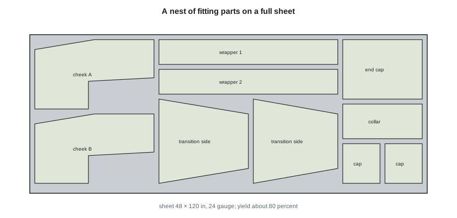
Nesting is the art and science of arranging parts on a sheet to waste as little metal as possible while keeping the cutting safe and the parts easy to sort. Nesting software tries thousands of arrangements, rotating and mirroring parts where the material allows, and places small parts inside the holes and gaps of large ones. It keeps a minimum gap between parts so the kerf of one does not cut into another and so the sheet does not warp from heat, and it sequences the cuts so the skeleton stays stiff until the end. Good nests on fitting work might use roughly 75 to 85 percent of a sheet; straight panels nest better than odd shapes.
# Nest yield and sheet count for a batch of fittings (illustrative)
import math
sheet_w, sheet_l = 48, 120          # sheet size, in
parts_area = 925                       # total area of flat parts in the batch, ft2
target_yield = 0.80                      # expected nest yield
sheet_area = sheet_w * sheet_l / 144
sheets = math.ceil(parts_area / (sheet_area * target_yield))
actual = parts_area / (sheets * sheet_area)
print(f"sheet area {sheet_area:.2f} ft2; sheets needed {sheets}; actual yield {actual:.1%}")
remnant = sheets * sheet_area - parts_area
print(f"skeleton and offcut {remnant:.1f} ft2")sheet area 40.00 ft2; sheets needed 29; actual yield 79.7% skeleton and offcut 235.0 ft2
Remnants are partly used sheets with a useful area left over. Keelson labels remnants with their gauge and size and stores them in a rack so the nesting software can use them on the next job, which raises the effective yield. Skeletons and small offcuts go to the scrap bin and are sold to a scrap dealer, which recovers a little of their value. Halima uses the shop's actual yield, including remnant reuse, in her estimates, as described in Lesson 7.
Cut speed, quality and time
Cutting speed depends on the material, thickness and amperage, and the torch manufacturer publishes cut charts for each combination. Too fast and the arc lags, leaving dross on the bottom edge and possibly failing to cut through; too slow and the cut widens, the edge melts back and heavy dross forms. Galvanized coatings produce more fume and can leave a rougher edge than plain steel. For thin sheet, a table might cut several meters per minute, or a few hundred inches per minute, so the time per fitting is often dominated by pierces, rapid moves and loading rather than by the cutting itself.
# Estimated cutting time for one nest (illustrative)
cut_length = 2440        # total cut length in the nest, in
speed = 240             # cutting speed, in per minute
pierces = 48           # one per part outline and hole
pierce_time = 0.6        # seconds per pierce including torch height sensing
rapids = 1500            # total rapid travel, in
rapid_speed = 800       # in per minute
load_unload = 4.0        # minutes per sheet
t = cut_length / speed + pierces * pierce_time / 60 + rapids / rapid_speed + load_unload
print(f"cutting {cut_length / speed:.1f} min, pierces {pierces * pierce_time / 60:.1f} min, "
      f"rapids {rapids / rapid_speed:.1f} min, handling {load_unload:.1f} min")
print(f"total about {t:.1f} minutes for this sheet")cutting 10.2 min, pierces 0.5 min, rapids 1.9 min, handling 4.0 min total about 16.5 minutes for this sheet
The calculation shows why shop schedulers think in sheets and nests, not in fittings. At Eastgate, Walt estimated table time per sheet for each gauge and used the number of nested sheets per floor to plan how many shifts the table needed, as Lesson 10 explains.
Cutting other materials
Stainless steel for the Eastgate isolation and laboratory exhaust is cut on the same table with a different process setup, often a different gas mix and consumables, to reduce discoloration and dross. Stainless parts are kept separate from carbon steel scrap and from carbon steel tools to avoid contamination that would cause rust spots, as SMW-230 explained. Aluminum cuts easily but reflects heat and needs its own cut chart. Copper for architectural work, such as the St. Brendan's roof, is usually sheared or cut on other machines, because the thin soft sheet is easily distorted by plasma heat and the finished edges are visible.
Safety at the plasma table
Plasma cutting produces intense ultraviolet light, very hot metal, sparks, noise and metal fume, and it uses high voltage. The table's own enclosure, curtains and downdraft extraction control most of the hazards, but operators still wear eye protection with a suitable shade when viewing the arc, hearing protection where the noise requires it, gloves for handling hot or sharp parts, and safety footwear. Galvanized and stainless fumes are hazardous, as SMW-230 covered, so the downdraft system and its collector must be working, and the collector is maintained and emptied on a schedule. A fire watch and good housekeeping matter too: oily rags, cardboard and dust near a plasma table are a fire risk.
Electrical hazards are controlled by the machine's guarding and by lockout before any work inside the torch or power supply, following OSHA's control of hazardous energy rules. Only trained operators run the table, and the shop's written procedure covers start-up checks, consumable changes, collision recovery and emergency stops.
Worked problem
How many sheets for a floor's fittings
The level 3 fittings in 24 gauge need flat parts with a total area of 925 sq ft. Sheets are 48 × 120 in and the expected yield is 80 percent. How many sheets are needed?
Show solution
- Sheet area: 48 × 120 / 144 = 40.0 sq ft.
- Usable area per sheet at 80 percent: 32.0 sq ft.
- Sheets: 925 / 32.0 = 28.9, so 29 sheets.
- Actual yield: 925 / (29 × 40.0) = 79.7 percent.
Answer: 29 sheets. The code example gives the same count and yield.
Common mistakes
MistakeSetting the wrong kerf compensation.
InsteadCheck the kerf on a test cut and confirm the control offsets half a kerf correctly.
MistakeRunning worn consumables to the end.
InsteadReplace consumables on a pierce-count schedule and check cut quality each shift.
MistakeCutting with the downdraft extraction off.
InsteadNever cut without the fume extraction running and maintained.
MistakeMixing stainless and carbon steel scrap and tools.
InsteadKeep stainless separate to avoid contamination and rust spots.
MistakeEstimating table time from cut length alone.
InsteadInclude pierces, rapid moves and loading, which dominate on thin sheet.
Summary and key terms
- Plasma cutting uses an electric arc and a gas jet to melt and blow out conductive metal.
- The control offsets the torch by half the kerf so parts come out at the right size.
- Fabrication software unfolds fittings into flat parts with allowances and tags, then nests them on sheets.
- Programs contain rapid moves, pierces, cutting moves at a feed rate, lead-ins and markings.
- Yield, remnants and scrap affect cost; table time depends on pierces and handling as well as cut length.
- Fume extraction, eye and hearing protection, fire watch and lockout keep the table safe.
- CNC
- Computer numerical control: a machine moved by a program.
- Plasma
- An electrically conducting gas hot enough to melt metal.
- Kerf
- The width of material removed by the cut.
- Nest
- An arrangement of flat parts on a sheet for cutting.
- Remnant
- A partly used sheet with a useful area left, stored for reuse.
- Consumables
- The torch parts that wear out, such as the electrode and nozzle.
Practice problems
Work each problem on paper first, then reveal the answer to check.
Why does the control move the torch half a kerf outside a part outline?
Show answer
So the material removed by the cut lies outside the part and the part is cut to the correct size.
Name three ways to raise nesting yield.
Show answer
Any three of: rotate and mirror parts, place small parts in gaps, combine fittings from many areas in one nest, reuse remnants, keep gaps to the minimum safe size.
Why is stainless kept separate from carbon steel at the table?
Show answer
To avoid contamination that causes rust spots and to suit its own process setup.
What usually dominates the time to cut a nest of thin fittings?
Show answer
Pierces, rapid moves and loading and unloading, more than cutting speed.
Lesson quiz · 5 questions
Score 60% or more to complete this lesson.
Create a free account to save your progress, take quizzes and earn a certificate.