
SMW-420 · Lesson 2 of 12 · 19 min
Drafting standards and sheet metal symbols
A shop drawing is only useful if everyone who reads it understands it the same way. The engineer reviewing it, the shop foreman releasing it to the coil line, the operator setting up the plasma table and the lead hand in the ceiling all need to read the same symbols, the same dimensions and the same tags without phoning the drawing office. That shared language is what drafting standards provide. This lesson covers the conventions Keelson uses: drawing scales, how duct is shown and dimensioned, standard fitting names and codes, layers and line types, title blocks and revision control. Kai spent his second week in Lin Zhao's office learning to read and mark up Keelson's standard sheets before he was allowed to draw anything himself.
Scales, views and units
Duct shop drawings are mostly plan views at a scale large enough to show double-line duct with readable dimensions. Keelson draws floor plans at 1/4 in = 1 ft, mechanical rooms and congested areas at 1/2 in = 1 ft, and shows sections wherever several services cross or the duct changes elevation. A section cut through a crowded corridor ceiling is often the clearest way to show the engineer and the other trades exactly what goes where, from the slab above down to the ceiling grid. Riser diagrams show vertical shafts, and isometric views help with complex fittings and offsets.
US projects are drawn in inches and feet. Duct sizes are given in inches, width first and depth second, so a 24 × 16 duct is 24 in wide in the plan view and 16 in deep. Elevations are given in feet and inches above the finished floor, such as BOD 10'-2" for the bottom of duct. Some equipment arrives with metric data, so detailers must be comfortable converting, but the shop drawing itself uses one unit system consistently.
Width first is not a law of nature; it is a convention, and the drawing notes should state it. A duct described as 24 × 16 on a plan is assumed to be 600 wide as seen in plan and 400 deep. If the duct is turned on its side to pass under a beam, the size on the drawing changes to 16 × 24 even though it is the same piece of metal. Many duct errors in the field come from a fitting built or hung the wrong way round because someone read a size backwards.
How duct is drawn
In plan, rectangular duct is drawn as two parallel lines at its true width, and round duct as two lines with a center line. The size is written beside or inside the duct. A diagonal cross or a single diagonal line in a section of the duct is commonly used to show which way the duct runs in the vertical direction: a cross for supply or a duct turning up, a single diagonal for return or exhaust or a duct turning down, depending on the legend. Every set of drawings has a legend sheet, and on Keelson's drawings that legend is the first sheet in each package.
Insulation and lining change the outside dimensions. The duct size on the drawing is normally the inside clear dimension when the duct is lined, so that the airflow area is right, and the outside dimension is larger by twice the liner thickness plus the metal. Externally wrapped duct takes more room in the ceiling than its sheet metal size suggests. Lin's drawings note the insulation type on each run and draw the outside of insulation in a lighter line, so coordination checks use the real space taken.
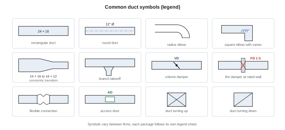
Dimensions and elevations
A shop drawing must give the installer enough dimensions to locate every run without scaling the drawing. Keelson dimensions duct runs to building gridlines, not to walls, because gridlines are surveyed and walls may not yet exist when the hangers go in. Each run also carries a bottom-of-duct elevation, abbreviated BOD, so the field can set hanger rods to the right length before the duct arrives. Where the bottom of duct changes, such as at a drop under a beam, the drawing shows the new elevation and the fitting that makes the change.
Lengths of straight duct are usually not dimensioned joint by joint on the plan; instead, the fabrication list breaks each run into standard joints and the drawing shows the joint marks. Fittings are dimensioned with their throat, heel and offset dimensions in the fitting schedule rather than on the plan. Keeping detailed fabrication dimensions off the plan keeps the plan readable while the fabrication data stays exact.
# Bottom-of-duct elevation check under a beam
bos = 124.0            # bottom of steel above finished floor, in
fire_proofing = 1.0   # spray fireproofing thickness, in
hanger_clear = 3.0    # space for trapeze angle and nuts below the beam, in
insulation = 1.0      # external insulation thickness, in
duct_depth = 16      # sheet metal depth of the duct, in
bod = bos - fire_proofing - hanger_clear - insulation - duct_depth - insulation
print(f"highest possible bottom of duct: {bod:.1f} in")
ceiling = 96
space = bod - ceiling
print(f"space left above the ceiling grid: {space:.1f} in")
print("fits" if space >= 6 else "does not fit: change duct shape or route")highest possible bottom of duct: 102.0 in space left above the ceiling grid: 6.0 in fits
The calculation shows why Lin's RFI from Lesson 1 proposed a flatter duct under the beam. With fireproofing, hanger space and insulation, the deep duct leaves too little room above the ceiling for sprinkler branches and lights. Detailers run this kind of check constantly, and the coordination model in Lesson 3 does it automatically, but the arithmetic is the same.
Fitting names and fitting codes
Every shop has names for its fittings, and those names must be standard enough that the drawing office, the shop and the field mean the same thing. Keelson follows the fitting types and names in the duct construction standard the specification calls for, together with its own catalog of fitting codes used by its fabrication software. A radius elbow, a square elbow with turning vanes, a transition, an offset, an ogee offset, a tee, a wye, a shoe tap or a bellmouth each has a code, a set of input dimensions and a known pattern.
| Keelson code (example) | Fitting | Key dimensions |
|---|---|---|
| ST | Straight duct | Width, depth, length, gauge, joint type |
| RE | Radius elbow | Width, depth, throat radius, angle |
| SE | Square elbow with vanes | Width, depth, vane type |
| TR | Transition | Two end sizes, length, offsets |
| OF | Offset | Size, offset distance, length |
| TP | Branch tap | Branch size, main size, tap style |
| EC | End cap | Width, depth |
Fitting codes matter because they connect the drawing to the shop's machines. When Lin tags a fitting RE-3-014 on level 3, the fabrication software knows the fitting type, its dimensions and its gauge, can generate the flat pattern from the SMW-210 layout methods, can place it on a plasma nest and can print a label. The field crew sees the same tag on the drawing and on the metal. A tag that appears on the drawing but not in the fabrication list, or the other way round, is a gap that will become a missing piece on site.
Layers, line types and colors
Shop drawings are prepared in a drafting or modeling program, and Keelson's drawing standard sets how information is organized. Each kind of object sits on its own layer: supply duct, return duct, exhaust duct, grease duct, insulation outline, hangers, accessories, dimensions, tags, notes and the background architectural and structural drawings supplied by others. Layers can be turned on and off, which lets a detailer print a clean hanger layout for the field or a coordination sheet showing only duct and structure.
Line types and weights carry meaning too. The duct outline is a heavy line; the insulation outline is lighter; background walls and structure are screened back so the new work stands out; hidden lines are dashed. Colors are used on screen and in coordination models to tell the systems apart, though a shop drawing must still read correctly when printed in black and white, because the field copy on a clipboard rarely is in color.
Title blocks, sheet numbers and revisions
Every sheet has a title block. Keelson's carries the project name, the owner, the general and mechanical contractors, the area and floor, the drawing title, the sheet number, the scale, the drafter and checker initials, the date and the revision table. The sheet numbering follows a pattern so that anyone can find a sheet: for example M-SM-301 might be the sheet metal plan for level 3, area 1. A drawing without a clear revision number is dangerous on a job site, because someone will eventually hang duct from an old copy.
Revision control is a discipline, not a formality. When a drawing changes, the detailer clouds the change, adds a revision triangle with the revision number next to it, records the revision and its reason in the title block table, and reissues the drawing with a transmittal. Superseded prints in the shop and on site are collected or stamped void. Keelson keeps the current set in a document control system that the field reads on tablets, which reduces the risk of old prints, but the paper set in the site office still has to be updated by hand.
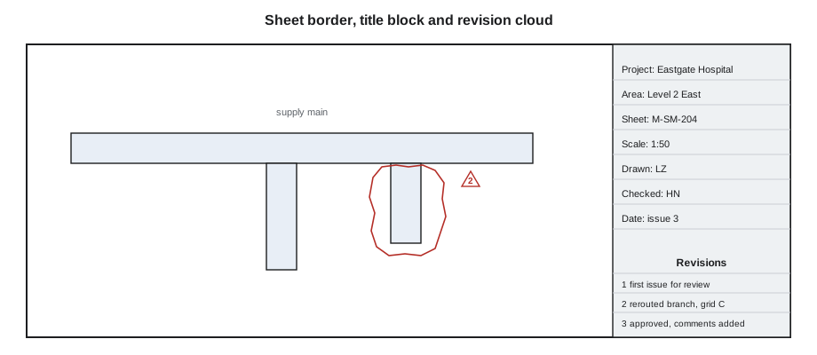
Checking a drawing
Before a drawing leaves the office, a second detailer checks it. Keelson uses a checklist: sizes match the design or an approved RFI; gauges and joints match the pressure class; elevations work with structure and ceilings; dampers, access doors and fire-rated details are shown where required; hangers are shown at the spacing in the support standard; every fitting has a tag that exists in the fabrication list; notes are clear; the legend and title block are complete. The checker marks problems in red and the drafter corrects them in a different color, so the history of the check is visible. Kai's first job was to check two of Lin's sheets, and he found a reversed size on a branch that she had missed.
Worked problem
Reading a dimension and a tag
On sheet M-SM-302 a run is labeled 36 × 10, BOD 8'-8", with fittings TR-2-031 and OF-2-032 where it drops below a beam. What does each item tell the field crew?
Show solution
- 36 × 10 is the duct's width in plan and its depth: the duct is wide and shallow.
- BOD 8'-8" is the bottom of the duct above finished floor, so the hanger rods are cut to suit.
- TR-2-031 is a transition on level 2, number 31 in the fitting list, changing the duct to the flat shape.
- OF-2-032 is the offset that drops the duct below the beam; its dimensions are in the fitting schedule, not on the plan.
Answer: The plan locates the duct; the tags link to exact fabrication data, so the crew finds the right fittings on the pallet and hangs them at the right height.
Drawing for the people who use the sheet
A shop drawing has several readers, and Lin keeps all of them in mind. The engineer reviews it for compliance with the design; the general contractor checks it against other trades and the architecture; the shop reads it for fitting sizes and tags; and the field crew reads it in a ceiling with poor light. Clear line weights, text large enough to read when the sheet is printed at half size, consistent tag positions and a legend on every package make the same sheet work for all of them.
Common mistakes
MistakeReading a duct size backwards.
InsteadWidth is the plan dimension, depth is the vertical dimension, and turning a duct changes the order of its size.
MistakeDimensioning duct to walls that are not yet built.
InsteadDimension to gridlines, which are surveyed early.
MistakeForgetting insulation in clearance checks.
InsteadCoordinate using the outside of insulation, not the sheet metal size.
MistakeTagging a fitting on the drawing that is not in the fabrication list.
InsteadCheck that every tag on the drawing exists in the list and the other way round.
MistakeReissuing a changed drawing without a cloud and a revision number.
InsteadCloud the change, number the revision, record it and collect old prints.
Summary and key terms
- Shop drawings use consistent scales, views and units, with width first and depth second for rectangular duct.
- The legend sheet defines symbols; insulation and lining change the real space a duct takes.
- Runs are dimensioned to gridlines with bottom-of-duct elevations.
- Fitting codes connect the drawing to the fabrication software and to the tags on the metal.
- Layers, line types and colors organize information; prints must still read in black and white.
- Title blocks, revision clouds and document control keep everyone working from the current drawing.
- BOD
- Bottom of duct elevation, the height of the underside of the duct above a reference such as finished floor.
- Gridline
- A surveyed reference line of the building structure used for dimensioning.
- Fitting code
- A short code identifying a fitting type and its fabrication pattern.
- Layer
- A named group of drawing objects that can be shown, hidden or printed together.
- Revision cloud
- A wavy outline drawn around a change on a reissued drawing.
- Title block
- The panel on a drawing sheet recording the project, sheet, scale, people and revisions.
Practice problems
Work each problem on paper first, then reveal the answer to check.
A duct labeled 20 × 12 is rotated to pass under a beam. What size will the drawing show?
Show answer
12 × 20: the width in plan and depth swap.
Why are runs dimensioned to gridlines?
Show answer
Gridlines are surveyed early and reliable; walls may not exist when hangers are set.
What three things record a drawing revision?
Show answer
A cloud around the change, a revision triangle and number, and an entry in the title block revision table.
Why does the fitting tag matter to the field?
Show answer
It matches the label on the fabricated fitting, so the crew can find and place the right piece.
Lesson quiz · 5 questions
Score 60% or more to complete this lesson.
Create a free account to save your progress, take quizzes and earn a certificate.