
SMW-420 · Lesson 3 of 12 · 19 min
Coordination models and BIM for sheet metal
Twenty years ago, Keelson coordinated its ductwork by laying printed sheet metal drawings over the sprinkler, plumbing and electrical drawings on a light table and looking for places where lines crossed. Today the same job is done in three dimensions on a screen, with every trade's work combined into one coordination model. The tools have changed the speed and accuracy of coordination, but not its purpose: to prove that everything fits before anyone cuts metal or drills a hole. This lesson explains building information modeling, or BIM, from a sheet metal contractor's point of view, and how Lin Zhao's team uses it on the Eastgate Hospital addition.
What a BIM model is
A building information model is a digital model of a building in which each object is not just a shape but carries information about what it is. A duct in the model is not merely a box; it knows its system, its size, its material and gauge, its insulation, its connector types and its fitting code. A fire damper object knows its rating and its manufacturer. Drawings, schedules and quantities can all be produced from the same model, so a change made once shows up everywhere. That is the main advantage over two-dimensional drafting, where a change to a plan might not be carried into a section or a schedule.
On a project like Eastgate there is not one model but many. The architect and the structural and mechanical engineers each produce design models. Each trade contractor produces its own construction or fabrication model of its work: Keelson for ductwork, Northpoint Mechanical for piping, the sprinkler contractor, the electrical contractor and so on. The general contractor's coordinator combines them in a federated model, in which each trade's model is linked rather than merged, so each trade keeps control of its own work. Common software for this includes design authoring tools used by engineers and detailers, fabrication add-ons that hold real manufacturer and shop content, and model review and clash tools used for coordination.
Models are exchanged in agreed formats. Native files from the authoring software are common within a trade. For exchange between different programs, many projects use IFC, the open Industry Foundation Classes format, which is published as an international standard and can be read by most BIM tools. The BIM execution plan for the project, written early by the general contractor and signed by the trades, sets out which formats, coordinate system, levels of detail, file naming and meeting schedule everyone will use.
Level of development
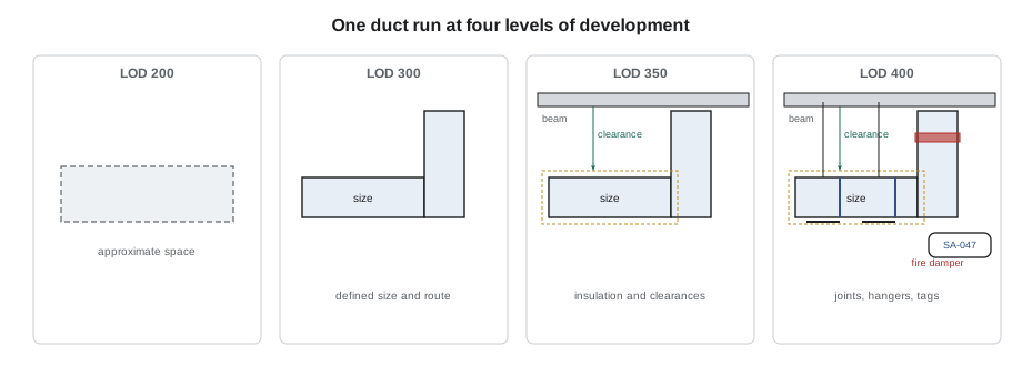
Not every model is detailed enough to build from. The construction industry uses a scale called level of development, or LOD, to describe how much the information in a model element can be relied on. The scale published by the BIMForum, widely used in North America, runs from LOD 100, a symbol or rough mass, through LOD 200 with approximate size and location, LOD 300 with specific size, shape and location from the design, to LOD 400, where the element is modeled with enough detail and accuracy to be fabricated and installed. A further level is sometimes used for verified as-built conditions.
| LOD (typical meaning) | For a duct | Who usually models it |
|---|---|---|
| 100 | A note or block showing that duct exists in an area | Early design |
| 200 | Approximate size and route | Schematic design |
| 300 | Specific size, route and elevation from the design | Engineer's design model |
| 350 | Plus connections and clearances to other systems | Coordination |
| 400 | Fabrication detail: joints, gauges, fittings, hangers | Sheet metal contractor |
The engineer's design model for Eastgate is roughly LOD 300: the ducts are sized and routed, but without joints, real fittings or hangers. Keelson's fabrication model has to reach LOD 400. Lin's team rebuilds the ductwork with real connectors, joint lengths, fitting patterns from Keelson's catalog, insulation thickness, hangers and inserts. That model becomes the source of the shop drawings, the fabrication lists and the CNC data. Kai was surprised how much of the engineer's model had to be redrawn; Lin explained that the design model is right about intent but usually not buildable in detail.
Clash detection
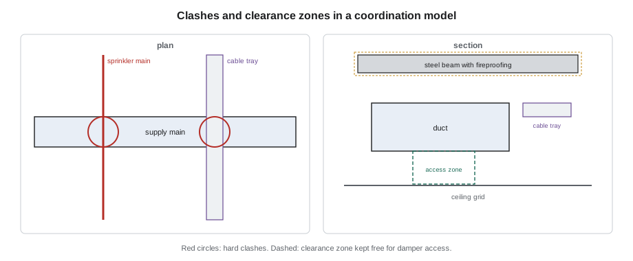
Clash detection is the automatic search for places where objects in the federated model occupy the same space. A hard clash is two objects physically overlapping, such as a duct passing through a beam or a sprinkler main running through a duct. A soft clash, or clearance clash, is an object entering a zone that must be kept clear, such as the access space in front of a fire damper's access door, the service clearance below a terminal unit or the insulation thickness around a chilled-water pipe. A workflow clash involves timing, such as a duct that can only be installed if a pipe is hung first.
Clash tools are good at finding problems and bad at judging them. A first clash run on a hospital floor can produce thousands of clashes, many of them trivial or duplicates: a hanger rod touching a conduit, or a duct crossing a pipe that is really above it in a different version. Coordinators filter clashes by system and size, group them by location, and set tolerances so that small overlaps that the field can easily solve do not clutter the list. What matters is that the important clashes are found, assigned to a trade and solved before the drawings are signed off.
# Sorting a clash report by trade and priority
clashes = [("duct", "beam", "hard", 14), ("duct", "sprinkler main", "hard", 37),
           ("duct", "cable tray", "hard", 22), ("hanger rod", "conduit", "hard", 160),
           ("damper access zone", "pipe", "clearance", 9), ("duct", "light fixture", "clearance", 48)]
priority = {"beam": 1, "sprinkler main": 2, "pipe": 2, "cable tray": 3, "light fixture": 3, "conduit": 4}
total = sum(c[3] for c in clashes)
for a, b, kind, n in sorted(clashes, key=lambda c: (priority[c[1]], -c[3])):
    print(f"{a:20s} vs {b:15s} {kind:9s} {n:4d}  priority {priority[b]}")
print(f"total {total}; hanger and conduit touches left for the field: {160}")duct vs beam hard 14 priority 1 duct vs sprinkler main hard 37 priority 2 damper access zone vs pipe clearance 9 priority 2 duct vs light fixture clearance 48 priority 3 duct vs cable tray hard 22 priority 3 hanger rod vs conduit hard 160 priority 4 total 290; hanger and conduit touches left for the field: 160
In this example most of the raw clashes are hanger rods touching conduit, which the electricians and Keelson's field crew can solve by shifting a rod or a conduit a few centimeters. The duct-to-beam clashes come first, because only a change in the duct or a structural approval can solve them; then the sprinkler mains and the damper access zones. The coordinator's job is to keep the meeting focused on the clashes that require a decision.
The coordination meeting
At Eastgate, coordination runs floor by floor. Each week the trades upload their latest models, Northpoint's coordinator Arjun Mehta runs the clash tests, and the trades meet with the model on a large screen. They work through the clash groups area by area, agree who moves what, and record each decision with a screenshot and an owner. Lin attends for Keelson, often with Sean Doucette, the field foreman, because some decisions depend on how the duct will actually be hung. When an area is clean, every trade signs it off, and from then on any change in that area requires another round of coordination.
Two habits make the meetings work. The first is to bring solutions, not complaints: Lin arrives with a proposed reroute for each duct clash, already checked against the duct sizes and pressure drop. The second is to respect the order of priority described in Lesson 1, while remembering that the cheapest solution for the project is not always the one that keeps a particular trade's work unchanged. Sometimes it is cheaper for the sprinkler main to drop 6 in than for a large duct to change shape for 65 ft.
Fabrication-ready models
Once an area is coordinated, the LOD 400 model drives fabrication. Each straight joint and fitting in the model carries its fitting code, dimensions, gauge, connector types, sealant class and a unique tag. Keelson's fabrication software exports this information to the shop: cut lists for the coil line, pattern files for the plasma table, labels for each piece and assembly spool sheets. Lessons 8 and 9 follow that data onto the machines. Because the same model also produces the shop drawings, the drawing, the label on the metal and the location in the building all agree, provided nobody edits one without the others.
The model also feeds the field. Hanger and insert locations from the model are exported as points that a layout crew can set out with a robotic total station, or printed as dimensioned layout sheets. Sean's crew on Eastgate set the concrete inserts for levels 2 and 3 from model points before the slabs were poured, so that the duct supports land exactly where the duct is drawn. That only works if the model is right and has been coordinated with the structural engineer's slab openings and embedded items.
Limits and good practice
A model is only as good as the information put into it. Structural steel modeled from the design drawings may be off by the amount that the fabricator later adjusts; fireproofing is often not modeled at all; existing buildings are rarely modeled accurately unless they are scanned. On renovations and connections to existing buildings, Keelson uses laser scans of the existing ceiling space, like those described in the geomatics courses, to bring real conditions into the model. On Eastgate, the connection to the existing hospital corridor was scanned before detailing, and the scan showed two existing ducts that the old record drawings had placed 1 ft away from where they really were.
Good modeling practice is mostly discipline: model to the agreed coordinate system and levels; keep each system on its own category or layer; use real fitting content rather than generic boxes; model insulation and hangers; name files and tag objects to the BIM execution plan; and never edit another trade's model. Keelson's checklist also requires that every change after sign-off be logged, with the reason and who approved it, because a late change in one area can reopen clashes that were thought to be solved.
Worked problem
Choosing who moves
On Eastgate level 2, a 40 × 18 supply main clashes with a 6 in sprinkler main for 60 ft along a corridor. Moving the duct requires flattening it to 56 × 12, adding two transitions and raising the fan's static pressure slightly. Dropping the sprinkler main 8 in requires two offsets and no other changes, and still clears the ceiling. Which should move?
Show solution
- Check fixed items: there is no structural conflict either way.
- Compare impacts: the duct change adds fittings and pressure drop over a long run; the sprinkler change adds two offsets.
- Check clearances: the lowered sprinkler main still clears the ceiling and lights.
- Agree in the meeting and record the decision, with the sprinkler contractor as owner.
Answer: The sprinkler main moves. Coordination looks for the lowest-cost solution for the project, not for any one trade.
Keeping the model honest
A coordination model is only as good as the information in it. Lin checks that each trade's model is current before every clash run, that insulation and access zones are modeled, and that the reference points and levels match the project's survey control. When a field measurement shows the building differs from the model, for example a slab poured a little high or a beam moved during erection, the model is updated before more areas are released, so that the next shop drawings are drawn to the real building.
Common mistakes
MistakeTreating the engineer's design model as fabrication-ready.
InsteadRebuild the work at LOD 400 with real joints, fittings, insulation and hangers.
MistakeTrying to resolve every raw clash in the meeting.
InsteadFilter, group and prioritize clashes so decisions focus on the important ones.
MistakeEditing another trade's model to clear a clash.
InsteadAgree the change in coordination and let each trade change its own model.
MistakeForgetting fireproofing and insulation in the model.
InsteadModel them, or allow for them in clash tolerances.
MistakeChanging an area after sign-off without telling anyone.
InsteadLog every change and re-run coordination in that area.
Summary and key terms
- A BIM model carries information as well as geometry, so drawings, schedules and quantities stay consistent.
- Each trade models its own work; a federated model combines them for coordination, often exchanged through IFC.
- Level of development describes how far a model can be relied on; fabrication needs LOD 400.
- Clash detection finds hard, clearance and workflow clashes; people decide which matter.
- Coordinated LOD 400 models drive shop drawings, fabrication data and field layout.
- Real conditions, especially in existing buildings, should be captured by scanning.
- BIM
- Building information modeling: digital models whose objects carry data as well as shape.
- Federated model
- A combined model that links each trade's separate model for coordination.
- IFC
- Industry Foundation Classes, an open standard format for exchanging BIM data.
- LOD
- Level of development: how detailed and reliable a model element is.
- Hard clash
- Two model objects occupying the same space.
- BIM execution plan
- The project document setting out modeling standards, formats and responsibilities.
Practice problems
Work each problem on paper first, then reveal the answer to check.
What is the difference between a hard clash and a clearance clash?
Show answer
A hard clash is a physical overlap; a clearance clash is an object entering a zone that must be kept clear, such as an access zone.
Why does the sheet metal contractor rebuild ducts from the engineer's model?
Show answer
The design model shows intent at about LOD 300; fabrication needs real joints, fittings, gauges, insulation and hangers at LOD 400.
What does a federated model let each trade keep?
Show answer
Control of its own model, which is linked rather than merged.
Name one way the model helps the field crew.
Show answer
Hanger and insert locations exported as layout points or dimensioned layout sheets.
Lesson quiz · 5 questions
Score 60% or more to complete this lesson.
Create a free account to save your progress, take quizzes and earn a certificate.