
SMW-410 · Lesson 6 of 12 · 19 min
Local exhaust ventilation design
Lesson 1 showed that capturing a contaminant at its source uses far less air than diluting it in the room. This lesson shows how a local exhaust system is laid out and sized so the capture actually happens: how hoods are chosen, how much air each hood needs, how fast the air must move in the duct, and how the fan pressure is worked out. The method follows the approach used in the ACGIH manual Industrial Ventilation: A Manual of Recommended Practice for Design, the reference most engineers and hygienists use for this work. Designing the system is the engineer's job, but the sheet metal worker builds every hood and fitting in it, and the design only works if those are built as drawn.
The examples come from Ironbark Millwork, a cabinet and architectural woodwork shop on the edge of Cleveland run by its owner, Siobhan Kearney. Ironbark has grown from three portable dust collectors to a shop with a table saw, a panel saw, a planer, a jointer, two wide-belt and orbital sanding stations, a CNC router and a small finishing room. Siobhan has hired an engineering firm to design a central dust collection system, and Keelson has the contract to build and install it. The engineer is Tomasz Wrona, who has designed many woodshop systems and who explains his reasoning to Kai as they walk the shop.
Kinds of hoods
A hood is anything that shapes the airflow so the contaminant is drawn into the duct. There are three broad kinds. An enclosing hood surrounds the source almost completely, like a booth, a glovebox or the guard enclosure around a saw blade; it captures best for the least air, because the contaminant is already inside it. A capturing hood sits outside the source and must reach out with air to pull the contaminant in; slot hoods along a bench and flanged openings beside a machine are capturing hoods. A receiving hood sits where the process throws the contaminant, such as the hood behind a grinding wheel that catches the stream of particles, or a canopy above a hot process that receives the rising plume.
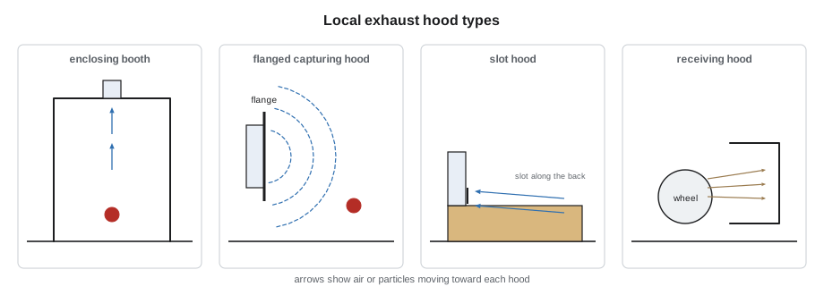
The rule Tomasz repeats is enclose as much as the work allows. Every bit of enclosure lets the hood use less air and capture better, as long as the operator can still do the job. Woodworking machines are good examples: most modern machines have dust hoods built into their guards and cabinets, with a collar sized for a branch duct, and the machine manufacturer states the airflow the hood needs. Tomasz uses those values for the machines and designs hoods only where the shop needs something the machines do not provide, such as the sanding stations and the wiping bench in the finishing room.
Capture velocity
A capturing hood must create, at the point where the contaminant is released, an air velocity toward the hood high enough to overcome the contaminant's own motion and any room air currents. That velocity is called the capture velocity. It depends on how the contaminant is released: vapor evaporating gently from a still surface needs little; dust thrown off a sander needs much more; a stream of particles from a grinding wheel needs the most. Room drafts from doors, fans and make-up air raise the capture velocity needed.
| How the contaminant is released | Examples | Typical capture velocity |
|---|---|---|
| With almost no velocity, into still air | Evaporation from tanks, wiping solvent | 50 to 100 fpm |
| At low velocity into moderately still air | Spray booths, intermittent filling, welding | 100 to 200 fpm |
| Active generation into rapid air motion | Sanding, conveyor loading, crushers | 200 to 500 fpm |
| High initial velocity into very rapid air motion | Grinding, abrasive blasting | 500 to 2,000 fpm |
Capture velocity falls off very quickly with distance from a hood opening. For a plain opening, the velocity at a distance equal to one hood diameter in front of the face is only about a tenth of the face velocity. That single fact is why hood position matters so much: a hood pulled back twice as far from the source needs roughly four times the airflow for the same capture.
This is the Dalla Valle equation for a plain round or square opening in free space. Q is the hood airflow, V is the capture velocity wanted at distance x in front of the face, and A is the face area of the hood. A flange around the opening, a flat collar that stops the hood drawing air from behind itself, cuts the airflow needed by about a quarter. The equation is approximate, but it shows the effect of distance clearly, and Tomasz uses it to check the hoods he designs.
# Capture airflow for a hood at different distances (Dalla Valle)
V = 200            # capture velocity wanted at the source, fpm
A = 0.65            # hood face area, ft2
for x in (0.5, 1.0, 1.5):     # distance from the face to the source, ft
    q_plain = V * (10 * x**2 + A)
    q_flanged = 0.75 * q_plain
print(f"x = {x} ft: plain {q_plain:.0f} cfm, flanged {q_flanged:.0f} cfm")x = 0.5 ft: plain 630 cfm, flanged 472 cfm x = 1.0 ft: plain 2130 cfm, flanged 1598 cfm x = 1.5 ft: plain 4630 cfm, flanged 3472 cfm
Moving the sanding hood from 6 in to 18 in from the work multiplies the airflow needed by more than five. When a sander operator pushes a hood out of the way because it is awkward, the system has not just lost a little performance; it has stopped capturing.
Slot hoods
A slot hood is a long, narrow opening along the edge of a bench or tank, often fed from a tapered plenum behind it so the velocity is even along its length. It pulls air across the work surface toward the slot. Slot hoods suit work spread along a length, such as the Ironbark wiping bench, where solvent evaporates from the whole surface. The airflow for a slot depends on its length, the capture velocity and the distance to the far edge of the work, and a flanged slot or a slot along a wall needs less than a free slot.
# Slot hood along the back of the wiping bench
L = 6        # slot length, ft
x = 2        # distance to the far edge of the work, ft
V = 80        # capture velocity, fpm
Q = 2.6 * L * V * x
print(f"slot hood airflow {Q:.0f} cfm")
print(f"compare with dilution of the same solvent in the whole room: 2543 cfm")slot hood airflow 2496 cfm compare with dilution of the same solvent in the whole room: 2543 cfm
The slot hood captures the wiping solvent at the bench for about 2,500 cfm, similar to the dilution rate from Lesson 1, but it keeps the solvent out of the worker's breathing zone instead of letting it spread through the room first, and the hygienist's measurements later show the exposure at the bench is a fraction of what dilution gave. Moving the work closer to the slot, by marking a working zone on the bench, would cut the airflow further.
Transport velocity
Once the contaminant is in the duct, the air must move fast enough to keep it moving. Gases and vapors stay mixed at any velocity, so their ducts are sized for reasonable pressure loss and noise. Dust is different: if the air slows down, particles drop out and settle in the bottom of the duct, building up until the duct chokes or, for combustible dust, creating a fuel layer for a fire or explosion. Each kind of dust has a minimum transport velocity, and dust ducts are sized to stay above it everywhere, including in the branches and at the far end of the main.
| Material in the duct | Typical minimum transport velocity |
|---|---|
| Gases, vapors, smoke | 1,000 to 2,000 fpm |
| Welding fume, fine light dust | 2,000 to 2,500 fpm |
| Fine sawdust and sanding dust | 3,500 to 4,000 fpm |
| Wood shavings and chips | 4,000 to 4,500 fpm |
| Heavy or moist dust | 4,500 fpm and more |
Transport velocity is why dust systems are noisy and use a lot of fan power, and why the branch and main sizes on Tomasz's drawing look small to anyone used to comfort ducts. It is also why Kai cannot substitute a larger fitting from the shelf: a branch one size up drops the velocity below transport, and dust settles in it.
Pressure losses by the velocity pressure method
The fan has to supply enough pressure to accelerate the air into the hood, overcome the hood entry loss, and overcome friction and fitting losses along the duct and through the collector. The velocity pressure method expresses each loss as a multiple of the velocity pressure in that part of the system. Hood entry losses have their own coefficients: a plain duct end loses close to one velocity pressure, a flanged opening about half, and a smooth bell-mouth entry very little. Elbows and branch entries have loss coefficients that depend on their radius and angle, which is why designers specify long-radius elbows and branches that join the main at shallow angles.
# Static pressure along one branch by the velocity pressure method
import math
Q = 1000             # branch airflow, cfm
D = 7             # branch diameter, in
area = math.pi * (D / 12) ** 2 / 4
V = Q  / area
VP = (V / 4005) ** 2
print(f"branch velocity {V:.0f} fpm, velocity pressure {VP:.2f} in. w.c.")
Fh = 0.49            # flanged hood entry loss coefficient
losses = {"hood entry and acceleration": 1 + Fh,
          "two 90-degree elbows, long radius": 2 * 0.27,
          "straight duct, 30 ft equivalent": 30 * 0.012,
          "branch entry at 30 degrees": 0.18}
total = 0
for name, k in losses.items():
    total += k * VP
    print(f"{name}: {k:.2f} VP")
print(f"branch static pressure at the main: {total:.2f} in. w.c.")branch velocity 3742 fpm, velocity pressure 0.87 in. w.c. hood entry and acceleration: 1.49 VP two 90-degree elbows, long radius: 0.54 VP straight duct, 30 ft equivalent: 0.36 VP branch entry at 30 degrees: 0.18 VP branch static pressure at the main: 2.24 in. w.c.
In a multi-branch system the designer works out the static pressure needed by each branch where it joins the main. Branches joining at the same point must need the same pressure, or the system will not deliver the design airflows. The designer balances them either by sizing each branch so its losses match, called balance by design, or by fitting blast gates that add resistance to the branches with too little loss. Balance by design is preferred for dust because it leaves no gate half closed to catch dust and no gate for a worker to adjust.
Building it as designed
Kai's checklist for the Ironbark system comes straight from these principles. Hoods are built and placed exactly as drawn, with flanges where shown. Branches enter the main from the side or top, at the angle shown, never at 90 degrees. Elbows are the radius shown. Duct diameters are the ones on the drawing, not the nearest fitting on the shelf. Joints are tight, because leaks in a negative-pressure dust system pull in air that lowers the velocity at the hoods. And clean-out doors are installed at the places Tomasz marked, so a choked branch can be cleared without cutting the duct.
Worked problem
Sizing the planer branch
The planer's dust hood needs 2,000 cfm, and shavings need a transport velocity of at least 4,000 fpm. What duct diameter should the branch be, and what velocity does it give?
Show solution
- Area needed: 2,000 ÷ 4,000 = 0.50 ft².
- Diameter: √(4 × 0.50 ÷ π) = 0.80 ft = 9.6 in.
- Choose the next size smaller so the velocity stays above transport: 9 in.
- Velocity: 2,000 ÷ (π × 0.75² ÷ 4) = 4,527 fpm, above the minimum.
Answer: A 9 in branch keeps the shavings moving; the next size up would drop below transport velocity.
Common mistakes
MistakePulling a capture hood back from the source to make room.
InsteadKeep the hood as close as the work allows; capture falls with the square of distance.
MistakeLeaving the flange off a hood because it looks unnecessary.
InsteadBuild the flange; it cuts the airflow needed by about a quarter.
MistakeUsing a larger branch than drawn because the fitting was in stock.
InsteadUse the drawn size so the velocity stays above transport.
MistakeJoining a branch to the main at 90 degrees.
InsteadUse the shallow branch angle on the drawing to reduce losses.
MistakeBalancing a dust system with half-closed blast gates.
InsteadPrefer balance by design; gates catch dust and get changed.
Summary and key terms
- Enclosing hoods capture best; capturing hoods must reach out; receiving hoods catch thrown or rising contaminant.
- Capture velocity depends on how the contaminant is released and on room drafts.
- Capture falls steeply with distance; a flanged hood needs about three quarters of the air of a plain one.
- Dust ducts are sized to stay above the transport velocity everywhere.
- The velocity pressure method expresses each loss as a multiple of velocity pressure.
- Branches meeting at a junction must need the same pressure; balance by design is preferred for dust.
- Capture velocity
- Air velocity at the source needed to draw the contaminant into the hood.
- Transport velocity
- Minimum duct velocity that keeps particles from settling.
- Flange
- A flat collar around a hood opening that stops it drawing air from behind.
- Hood entry loss
- Pressure lost as air enters a hood, expressed as a multiple of velocity pressure.
- Velocity pressure method
- Calculating losses as coefficients times the local velocity pressure.
- Balance by design
- Sizing branches so their pressure needs match without blast gates.
Practice problems
Work each problem on paper first, then reveal the answer to check.
A hood is moved from twice its diameter to four times its diameter from the source. Roughly how does the airflow needed change?
Show answer
It roughly quadruples, because airflow rises with the square of distance.
Why do dust ducts look small compared with comfort ducts of the same airflow?
Show answer
They are sized for a high transport velocity so dust stays airborne.
A branch carries 1,000 cfm in a 7 in duct. What is the velocity?
Show answer
1,000 ÷ (π × (7/12)² ÷ 4) = 3,742 fpm.
Why is balance by design preferred over blast gates in a dust system?
Show answer
No gate is left partly closed to catch dust, and nobody can change the balance by moving a gate.
Lesson quiz · 5 questions
Score 60% or more to complete this lesson.
Create a free account to save your progress, take quizzes and earn a certificate.