
ROB-450 · Lesson 3 of 12 · 25 min
Functional safety with ISO 13849-1
Most robot safeguards depend on a control system working correctly at the moment it is needed. A light curtain is useless if the relay behind it has welded contacts; an interlocked gate is useless if the robot controller ignores the signal. Functional safety is the part of overall safety that depends on safety-related control systems functioning correctly in response to their inputs. ISO 13849-1, Safety of machinery: Safety-related parts of control systems, Part 1: General principles for design, is the most widely used machinery standard for it, and its fourth edition was published in 2023. ROB-440 lesson 8 introduced performance levels, the risk graph and the addition of PFHd values along a chain. This lesson works through the full method behind the numbers: specifying safety functions, choosing architectures, calculating mean time to dangerous failure from component data, diagnostic coverage and common cause failure, and reading off the achieved performance level. The calculations are simplified for teaching; real designs use the standard's tables and validated tools such as SISTEMA.
Safety functions and their specification
A safety function is a function of a machine whose failure can result in an immediate increase of risk. Typical robot safety functions include safety-related stop on opening an interlocked guard, safety-related stop when a light curtain or scanner field is entered, prevention of unexpected start-up, safely limited speed, safely limited position or zone, monitored standstill, enabling device function and emergency stop. Each function is implemented by safety-related parts of the control system (SRP/CS): input devices, logic and output devices, plus the wiring and software that connect them.
The 2023 edition puts more weight on writing a safety requirements specification before design. For each safety function, the specification should state what triggers it, what the machine must do and how quickly, the required performance level (PLr), the operating modes in which it is active, how it is reset, what happens on loss of power, the interaction with other functions, and the environmental conditions. A vague specification such as stop the robot when the gate opens hides important choices: stop category 0 or 1, whether the gate should be locked until standstill, whether the robot may restart automatically when the gate closes (it should not, for a guard that people can walk through), and what happens if a door switch fails.
| Item in the specification | Example for a gate interlock |
|---|---|
| Trigger | Maintenance gate leaves its closed position |
| Safe state and response | Robot and conveyor brought to stop category 1 within 0.5 s; guard locking holds the gate closed until standstill is confirmed |
| PLr | PL d from the risk graph (S2, F1, P2) |
| Modes | All modes except manual reduced speed with enabling device, where a separate function applies |
| Reset | Manual reset from outside the cell, with a view of the whole cell, after the gate is closed |
| Faults | Single fault must not lead to loss of the function; faults detected at the next gate operation |
| Environment | Indoor, vibration from presses nearby, washdown not required |
Determining the required performance level
The required performance level is determined from the risk assessment using parameters for severity (S1 slight, normally reversible injury; S2 serious, normally irreversible injury or death), frequency and duration of exposure (F1 seldom to less often or short; F2 frequent to continuous or long), and possibility of avoiding the hazard or limiting harm (P1 possible under specific conditions; P2 scarcely possible). The risk graph, which ROB-440 showed, turns these into PLr a to e. The 2023 edition retains the graph and gives more guidance on choosing the parameters, including that the probability of a hazardous event occurring may justify lowering the PLr by one level in some situations, provided the reasoning is documented. Severity is never lowered by the existence of the safeguard being designed, since the purpose is to find out how good that safeguard must be.
Architectures: the categories
ISO 13849-1 describes designated architectures, called categories, that set the structure and fault behavior of the SRP/CS. The category is not a quality grade on its own. It combines with component reliability, diagnostics and protection against common cause failure to determine the performance level achieved.
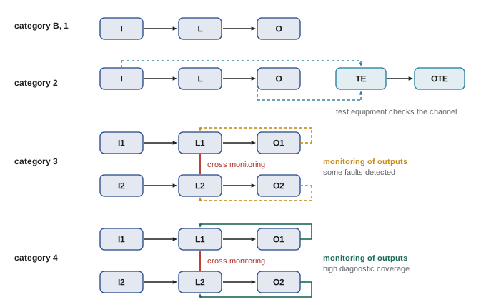
| Category | Structure and fault behavior | Requirements on MTTFd and DCavg | Typical maximum PL |
|---|---|---|---|
| B | Single channel; basic safety principles; a fault can cause loss of the function | MTTFd low to medium; no diagnostics | b |
| 1 | Single channel with well-tried components and principles | MTTFd high; no diagnostics | c |
| 2 | Single channel tested at suitable intervals by test equipment | DCavg low to medium; CCF measures | d |
| 3 | Redundant; a single fault does not cause loss of the function; some faults detected | DCavg low to medium; CCF measures | e (with high MTTFd and medium DC) |
| 4 | Redundant; single faults detected at or before the next demand; accumulation of faults does not cause loss | MTTFd high; DCavg high; CCF measures | e |
Well-tried components are those widely used in the past with successful results in similar applications, or made according to principles that show suitability and reliability, such as switches with positive opening contacts to IEC 60947-5-1, whose contacts are forced apart mechanically even if they weld. A single channel of well-tried components can be good enough for moderate risks, but cannot detect its own faults. For PL d and e, redundancy with monitoring is the usual answer.
Mean time to dangerous failure
MTTFd is the expected mean time before a component fails in a way that defeats the safety function. Electronic components have constant failure rates given by manufacturers, often as a dangerous failure rate \( \lambda_D \) per hour, with \( \mathrm{MTTF_D} = 1/\lambda_D \). Electromechanical, pneumatic and mechanical components wear with use, so their reliability is given as B10d, the number of operations after which 10 percent of a sample has failed dangerously. The standard converts B10d to MTTFd using the number of operations per year.
Here \( d_{op} \) is days of operation per year, \( h_{op} \) hours per day and \( t_{cycle} \) the mean time in seconds between operations of the component. A component should also not be used beyond \( T_{10D} = B_{10D}/n_{op} \) years, after which it must be replaced, which becomes a maintenance requirement in the manual. For a channel made of several components in series, the failure rates add, so the channel MTTFd follows from summing reciprocals. ISO 13849-1 classifies channel MTTFd as low (3 years to under 10), medium (10 to under 30) and high (30 to 100 years); values above 100 years are capped at 100 for the calculation, with a higher cap of 2,500 years allowed for category 4.
When the two channels of a redundant architecture differ, they are combined into one equivalent value using the symmetrization formula from the standard.
Here A and B are the MTTFd values of the two channels after capping.
Diagnostic coverage
Diagnostic coverage (DC) is the fraction of dangerous failures that diagnostics detect. A safety relay that checks whether both channels of an interlock switch change state together detects many faults, such as one contact welding or a wire short to supply. A contactor with mirror contacts fed back to the logic allows detection of a welded main contact before the next start. ISO 13849-1 tables give DC values for typical measures: none (below 60 percent), low (60 to under 90), medium (90 to under 99) and high (99 percent or more). For a whole function, an average is taken, weighted by failure rates.
A subtle point concerns several interlock switches wired in series to one safety relay input pair, a common and cheap arrangement on large cells with many doors. If one switch develops a fault and a different door is then opened, the relay may see a normal change and miss the fault, an effect called fault masking. ISO/TR 24119 explains how fault masking reduces the diagnostic coverage that can be claimed, often to low or none, depending on how many doors are typically opened together and how many switches are in series. For higher PLs, switches with individual diagnostics or safety network connections are preferred.
Common cause failure
Redundancy helps only if both channels do not fail together from the same cause, such as a voltage surge, overheating, contamination or a design error duplicated in both channels. For categories 2, 3 and 4, ISO 13849-1 requires a minimum score of 65 out of 100 points on its checklist of measures against common cause failure (CCF).
| Measure group | Examples | Points |
|---|---|---|
| Separation | Physical separation of signal paths, clearances and creepage distances | 15 |
| Diversity | Different technologies, components or design principles in the two channels | 20 |
| Design, application and experience | Protection against overvoltage and overcurrent; well-tried components | 15 + 5 |
| Assessment and analysis | Failure mode and effects analysis that considers common causes | 5 |
| Competence and training | Training of designers in common cause failures | 5 |
| Environment | Electromagnetic compatibility to relevant standards; protection against temperature, shock, vibration and humidity | 25 + 10 |
Putting it together
With the category, the MTTFd of each channel, DCavg and the CCF score, the simplified procedure of ISO 13849-1 gives the achieved PL from a chart, and Annex K of the standard tabulates the corresponding PFHd values. Software such as SISTEMA performs the same calculation for each subsystem and combines subsystems along the chain, which is where ROB-440's addition of PFHd values comes in. The following example applies the calculation steps by hand to a dual-channel gate interlock.
Worked problem
MTTFd of an interlock switch from B10d
A maintenance gate is opened on average every 15 minutes during two shifts of 8 hours, 230 days a year. Each of the two interlock switches has a B10d of 2,000,000 operations from the manufacturer's data. Find nop, MTTFd and T10d for one switch.
Show solution
- Cycle time: 15 min = 900 s.
- \( n_{op} = 230 \times 16 \times 3600 / 900 = 14\,720 \) operations per year.
- \( \mathrm{MTTF_D} = 2\,000\,000 / (0.1 \times 14\,720) \approx 1359 \) years, capped at 100 years for the calculation.
- \( T_{10D} = 2\,000\,000 / 14\,720 \approx 136 \) years, so wear is not a limit within the machine's life.
Answer: About 14,700 operations per year; MTTFd far above 100 years, so capped at 100; replacement for wear is not needed within normal machine life.
# ISO 13849-1 style calculation for a dual-channel gate interlock (simplified)
def nop(days, hours, t_cycle_s):
    return days * hours * 3600 / t_cycle_s
def mttfd_from_b10d(b10d, n):
    return b10d / (0.1 * n)
def channel(mttfds, cap=100):
    return min(cap, 1 / sum(1 / m for m in mttfds))
def symmetrize(a, b):
    return 2 / 3 * (a + b - 1 / (1 / a + 1 / b))
n_gate = nop(230, 16, 900)          # gate opened every 15 minutes
n_cont = nop(230, 16, 120)          # contactors switch every 2 minutes (cycle stops)
parts = {   # name: (MTTFd in years, DC)
    "switch 1": (mttfd_from_b10d(2.0e6, n_gate), 0.99),
    "switch 2": (mttfd_from_b10d(2.0e6, n_gate), 0.99),
    "relay ch1": (150.0, 0.99),
    "relay ch2": (150.0, 0.99),
    "contactor 1": (mttfd_from_b10d(1.3e6, n_cont), 0.99),
    "contactor 2": (mttfd_from_b10d(1.3e6, n_cont), 0.99),
}
for k, (m, dc) in parts.items():
    print(f"{k:12s} MTTFd = {m:8.1f} y  DC = {dc:.0%}")
ch1 = channel([parts["switch 1"][0], parts["relay ch1"][0], parts["contactor 1"][0]])
ch2 = channel([parts["switch 2"][0], parts["relay ch2"][0], parts["contactor 2"][0]])
m = symmetrize(ch1, ch2)
dcavg = sum(dc / mt for mt, dc in parts.values()) / sum(1 / mt for mt, _ in parts.values())
ccf = 15 + 0 + 15 + 5 + 5 + 5 + 25 + 10      # no diversity claimed
band = "high" if m >= 30 else "medium" if m >= 10 else "low"
dcband = "high" if dcavg >= 0.99 else "medium" if dcavg >= 0.90 else "low" if dcavg >= 0.60 else "none"
print(f"channel MTTFd: {ch1:.1f} y and {ch2:.1f} y; combined {m:.1f} y ({band})")
print(f"DCavg = {dcavg:.1%} ({dcband}); CCF score = {ccf} (>= 65 required)")switch 1 MTTFd = 1358.7 y DC = 99% switch 2 MTTFd = 1358.7 y DC = 99% relay ch1 MTTFd = 150.0 y DC = 99% relay ch2 MTTFd = 150.0 y DC = 99% contactor 1 MTTFd = 117.8 y DC = 99% contactor 2 MTTFd = 117.8 y DC = 99% channel MTTFd: 62.9 y and 62.9 y; combined 62.9 y (high) DCavg = 99.0% (high); CCF score = 80 (>= 65 required)
The contactors switch far more often than the gate switches, because the robot is stopped at every cycle in this design, so their MTTFd is lower and dominates each channel. The combined MTTFd is still high, the average diagnostic coverage is high because every component is monitored, and the CCF score exceeds 65. For a category 3 architecture with high MTTFd and at least medium DCavg, the simplified procedure gives PL e, comfortably meeting a PLr of d. If the switches had been wired in series with switches on other doors, fault masking could reduce the DC claimed for them, and the result would need to be recalculated.
| Category | DCavg | MTTFd low | MTTFd medium | MTTFd high |
|---|---|---|---|---|
| B | none | a | b | not allowed |
| 1 | none | not allowed | not allowed | c |
| 2 | low | a | b | c |
| 2 | medium | b | c | d |
| 3 | low | b | c | d |
| 3 | medium | c | d | e |
| 4 | high | not allowed | not allowed | e |
Beyond the numbers, ISO 13849-1 requires systematic measures: following basic and well-tried safety principles, managing software development, avoiding errors in specification and design, and validating under ISO 13849-2. Safety-related software has its own requirements, which increase with PL: a documented life cycle following a V-model, coding standards, restricted languages and libraries, reviews and testing. Most robot users write application software in a safety PLC's restricted language with certified function blocks, which reduces but does not remove the need for disciplined verification. Lesson 4 covers validation and the alternative IEC 62061 approach.
Common mistakes
MistakeEquating category with performance level.
InsteadA category is an architecture; PL also depends on MTTFd, DCavg and CCF measures.
MistakeUsing B10d directly as a lifetime without considering operating frequency.
InsteadConvert B10d with nop to MTTFd and check T10d as a replacement interval.
MistakeWiring many interlock switches in series and claiming high diagnostic coverage.
InsteadAccount for fault masking as described in ISO/TR 24119, or use individually monitored devices.
MistakeAssuming redundancy guarantees safety.
InsteadScore measures against common cause failure and reach at least 65 points for categories 2 to 4.
MistakeWriting the safety requirements specification after the design.
InsteadSpecify triggers, responses, PLr, modes, reset and fault behavior first, then design to meet them.
Summary and key terms
- ISO 13849-1:2023 is the main machinery standard for safety-related parts of control systems.
- Each safety function needs a written specification of trigger, response, PLr, modes, reset and fault behavior.
- PLr comes from severity, exposure and possibility of avoidance on the risk graph.
- Categories B, 1, 2, 3 and 4 define architectures from single channel without diagnostics to redundant with high diagnostics.
- MTTFd comes from failure rates or from B10d and operating frequency; channels combine by summing reciprocals and symmetrization.
- DCavg weights component diagnostics by failure rate; fault masking in series wiring reduces it.
- Categories 2 to 4 need at least 65 points against common cause failure; the simplified procedure then gives the achieved PL.
- Safety function
- A machine function whose failure can immediately increase risk.
- SRP/CS
- Safety-related parts of a control system.
- MTTFd
- Mean time to dangerous failure.
- B10d
- Operations after which 10 percent of components have failed dangerously.
- T10d
- Time in years after which a wearing component should be replaced, B10d divided by nop.
- DCavg
- Average diagnostic coverage of a safety function.
- CCF
- Common cause failure, which defeats both redundant channels at once.
- Fault masking
- A fault hidden when another device in series changes state, reducing diagnostic coverage.
- Well-tried component
- A component with proven successful use or designed to principles showing reliability.
Practice problems
Work each problem on paper first, then reveal the answer to check.
A component operates every 60 s for 20 h a day, 250 days a year. nop?
Show answer
\( 250 \times 20 \times 3600/60 = 300\,000 \) per year.
With B10d of 600,000 and nop of 300,000, find MTTFd and T10d.
Show answer
MTTFd = \( 600\,000/30\,000 = 20 \) years (medium); T10d = 2 years.
A channel has components with MTTFd 50, 100 and 200 years. Channel MTTFd?
Show answer
\( 1/(0.02 + 0.01 + 0.005) \approx 28.6 \) years (medium).
Symmetrize channels of 40 and 100 years.
Show answer
\( \tfrac{2}{3}(140 - 28.6) \approx 74.3 \) years.
What CCF score is required for category 3?
Show answer
At least 65 of 100 points.
Which category detects single faults at or before the next demand?
Show answer
Category 4.
What PL does the simplified procedure give for category 3, DCavg medium, MTTFd medium?
Show answer
PL d.
Why are positive opening contacts considered well-tried?
Show answer
They force contacts apart mechanically even if they have welded.
Lesson quiz · 5 questions
Score 60% or more to complete this lesson.
Create a free account to save your progress, take quizzes and earn a certificate.