
RAC-330 · Lesson 8 of 12 · 16 min
Airflow measurement and testing
In March, Dr. Singh agreed to Marcus's plan for the operatories, and the first step was to find out where the clinic's air was actually going. The packaged heat pump's start-up report from RAC-320 had recorded its total airflow, but nobody had measured the individual outlets since the original building was finished, and the clinic had been renovated twice since then. "Design drawings tell you what the engineer wanted," Marcus said, loading a flow hood into the truck. "The hood tells you what you've got."
This lesson describes the instruments and methods used to measure airflow in the field: pitot traverses, flow hoods, anemometers, the blower-table and temperature-rise methods, and how test and balance work is organized. It works through the clinic's airflow survey.
Why measure airflow
Almost every comfort and equipment problem has an airflow component. Too little air through a cooling coil lowers its capacity, ices it and raises the risk of slugging; too little through a heat pump's indoor coil in heating raises head pressure; too little to a room leaves it hot or cold; too much makes noise and drafts and can blow water off a coil. Ventilation rates, which lesson 11 covers, are airflows, and so are the exhaust rates that keep a kitchen or a sterilization room safe. Airflow is also the input to every capacity calculation in lesson 3 and RAC-320. Measuring it well is a core skill.
Airflow measurement in the field is less accurate than technicians often assume. A careful pitot traverse in a long straight duct can be within about 5 %; a flow hood reading on a well-chosen diffuser within about 5 to 10 %; estimates from blower tables or temperature rise often 10 to 20 % or worse. Good practice is to use two methods that should agree, and to investigate when they do not.
Pitot tube traverses
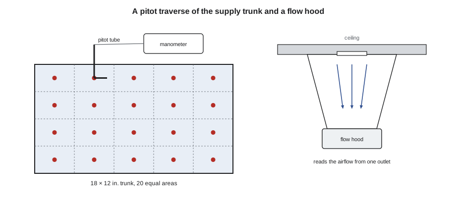
A pitot tube, with a digital manometer, measures velocity pressure at a point in a duct, and from it the velocity, as lesson 7 showed. Because the velocity varies across the duct, slow near the walls and fastest near the middle, a single reading is not enough. A traverse takes readings at a grid of points that each represent an equal part of the duct's area, averages the velocities, and multiplies by the area.
- Rectangular ducts: divide the cross-section into equal rectangles, typically at least 16 to 25 points for a trunk, with readings at the center of each, or use the log-Tchebycheff point positions that ASHRAE Standard 111 and the balancing standards give, which weight the points to account for the slower air near the walls.
- Round ducts: take readings along two diameters at right angles, at positions that divide the duct into equal-area rings.
- Location: in a straight section, ideally at least several duct diameters downstream and a couple upstream of any elbow, fan, damper or transition, where the flow is settled. Readings close to a disturbance are uneven and can even be negative.
- Average the velocities, not the pressures: square roots of individual velocity pressures, then the average. Averaging the pressures first overestimates the flow, more so the more uneven the profile.
At low velocities, under about 600 fpm, the velocity pressure is so small, a few thousandths of an inch of water, that manometer resolution and stray drafts dominate, so traverses work best in trunks rather than in branch ducts.
Flow hoods
A flow hood, or capture hood, is a fabric skirt on a frame that fits over a diffuser or grille, funnels all its air through a measuring grid at the base, and displays the airflow. Modern hoods have a manometer and a grid of averaging tubes, and many compensate for the resistance the hood adds, which otherwise reduces the airflow from the outlet slightly while it is being measured. Hoods are fast, which makes them the usual tool for measuring every outlet in a building.
They have limits. The skirt must fit the outlet and seal against the ceiling or wall; a large skirt on a small outlet or a gap at the ceiling gives wrong readings. Readings on outlets with very uneven or swirling discharge, such as some linear and swirl diffusers, may need correction factors from the hood maker. And the hood measures the air leaving one outlet, so the sum of outlets can differ from the trunk airflow because of leakage in the ducts between them, which is a useful measurement in itself.
Anemometers and other methods
Rotating vane anemometers measure velocity with a small propeller and are used at grilles, filter faces and coils, with the area and a manufacturer's correction factor for the grille type. Hot-wire and thermal anemometers measure velocity from the cooling of a heated sensor and are good at low velocities, in comfort measurements as in lesson 4, and in small ducts. Both give point velocities, not flows, and are more operator-dependent than a traverse or a hood.
Two indirect methods are common on residential systems.
- The blower-table method, as lesson 7 described: measure total external static pressure, read the airflow for the blower setting from the manufacturer's table, and correct for any components outside the cabinet. Many variable-speed air handlers display their own estimated airflow, which is useful but is the equipment's own estimate.
- The temperature-rise method, as RAC-320 lesson 10 showed: with electric heat of known output, measure the temperature rise and calculate the airflow from the sensible heat equation, with voltage and current measured, not assumed.
A third, more accurate residential method uses a calibrated fan or a pressure-matching device: a powered flow meter attached at the return or the filter slot that matches the pressure the system normally has there and reads the airflow directly. Some contractors and programs use it for commissioning; it is slower than a static pressure reading but much more reliable.
The clinic survey
Marcus and Theo started at the unit. They drilled a row of test holes in the long straight section of the supply trunk in the ceiling space, 18 × 12 in., five holes across the wide side at equal spacing, and took readings at four depths at each, twenty points in all. Then they put the hood over each of the clinic's six supply diffusers in turn, with the operatories' doors in their normal positions and the unit's blower at its normal speed. The script works out the trunk airflow from the traverse, compares it with the sum of the outlets, and compares each outlet with its design airflow.
import math
# pitot traverse of the 18 x 12 in. supply trunk, 4 rows x 5 columns at the centers of equal areas
vp = [
      [0.031, 0.039, 0.042, 0.039, 0.032],
      [0.036, 0.047, 0.050, 0.047, 0.037],
      [0.035, 0.046, 0.049, 0.046, 0.036],
      [0.030, 0.037, 0.040, 0.038, 0.031]]     # velocity pressure, in. w.c.
area = 18 * 12 / 144                           # ft2
vel = [4005 * math.sqrt(p) for row in vp for p in row]       # fpm at each point
v_avg = sum(vel) / len(vel)
flow = v_avg * area
wrong = 4005 * math.sqrt(sum(p for row in vp for p in row) / 20) * area
print(f"average velocity {v_avg:.0f} fpm, airflow {flow:,.0f} cfm")
print(f"(averaging the pressures first would give {wrong:,.0f} cfm, {wrong / flow - 1:+.1%})")
design = {"operatory 1": 235, "operatory 2": 235, "operatory 3": 235, "waiting room": 250, "office": 125, "sterilization": 120}
hood = {"operatory 1": 196, "operatory 2": 208, "operatory 3": 220, "waiting room": 292, "office": 140, "sterilization": 110}
total = sum(hood.values())
print(f"outlets total {total:,} cfm, {total / flow:.0%} of the trunk traverse")
for k in design:
    pct = hood[k] / design[k]
    flag = "" if 0.9 <= pct <= 1.1 else "  <- outside +/-10 %"
    print(f"{k:14s} design {design[k]:4d}  measured {hood[k]:4d}  {pct:4.0%}{flag}")
low = min(design, key=lambda k: hood[k] / design[k])
print(f"lowest ratio: {low}; set it as the reference and adjust the others to match its ratio first")average velocity 793 fpm, airflow 1,189 cfm (averaging the pressures first would give 1,192 cfm, +0.3%) outlets total 1,166 cfm, 98% of the trunk traverse operatory 1 design 235 measured 196 83% <- outside +/-10 % operatory 2 design 235 measured 208 89% <- outside +/-10 % operatory 3 design 235 measured 220 94% waiting room design 250 measured 292 117% <- outside +/-10 % office design 125 measured 140 112% <- outside +/-10 % sterilization design 120 measured 110 92% lowest ratio: operatory 1; set it as the reference and adjust the others to match its ratio first
The traverse gave about 1,190 cfm in the trunk, 99 % of the unit's 1,200 cfm design, and the outlets added up to about 1,170 cfm, so very little was leaking between them. Averaging the pressures instead of the velocities would have changed the answer by only 0.3 % here, because the flow in that straight section was even; in a disturbed profile the error can be several percent.
The outlets told the story. The waiting room was getting about 15 % more than its design and the office more than its share, while operatory 1, at the far end of the trunk, was getting only about 82 % of its design. The air the operatories needed was going to the rooms nearest the unit, which had the least resistance. Lesson 3's humidity problem was partly an airflow problem: the rooms with the highest moisture load were the ones receiving the least of the dry supply air.
Balancing
Balancing is adjusting dampers so each outlet gets its design airflow. A common method is proportional balancing, which ASHRAE and the balancing associations describe: find the outlet with the lowest ratio of measured to design airflow and leave its damper wide open; adjust the other outlets on the same branch to the same ratio, working from the outlet nearest the fan; then adjust the branch dampers to bring the branches to the same ratio; and finally adjust the fan speed to bring everything up to design together. Because adjusting one damper changes the flow to the others, proportional balancing reaches the result in fewer passes than adjusting each outlet to its design value one at a time.
Typical tolerances are ±10 % on each outlet and a few percent on the total, set by the design documents. Dampers should be at the branch takeoffs, not at the diffuser face where possible, because throttling at the face creates noise and disturbs the throw. After balancing, the damper positions are marked so they can be found and reset.
At the clinic, Marcus closed the waiting room and office branch dampers partway, left operatory 1 fully open, and brought the other operatories to the same ratio. A second pass and a small increase in the blower setting brought every outlet within 10 % of design.
Testing and balancing standards
Commercial testing, adjusting and balancing, TAB, is a specialty with its own certifications. In the United States, AABC, NEBB and TABB certify firms and technicians, and TAB requirements are written into commercial specifications. Their procedures cover instrument calibration, test methods, tolerances and reporting. ASHRAE Standard 111 covers measurement, testing, adjusting and balancing of building HVAC systems. For residential work, ACCA's quality installation standard and related programs set expectations for airflow, static pressure and duct testing at commissioning.
Instruments must be calibrated: manometers, flow hoods and anemometers drift, and certified balancers must have them checked at set intervals. Readings in a report should state the instrument and method, so that the next person can reproduce them.
The clinic's balance report went into the building file with the drawings, the readings before and after, and the damper positions. Dr. Singh asked whether the operatories would now feel better on humid afternoons; Marcus said they would be better, and that the dehumidification setting in lesson 12 would do the rest.
Common mistakes
MistakeAveraging velocity pressures before taking the square root.
InsteadConvert each reading to velocity, then average.
MistakeTraversing just after an elbow or damper.
InsteadChoose a long straight section with settled flow.
MistakeUsing a large hood skirt on a small outlet with gaps at the ceiling.
InsteadFit the skirt to the outlet and seal it.
MistakeBalancing each outlet to its design value one at a time.
InsteadUse proportional balancing from the lowest-ratio outlet.
MistakeThrottling airflow at the diffuser face.
InsteadUse branch dampers at the takeoffs where possible.
Summary and key terms
- Airflow is behind most comfort and equipment problems and is the input to capacity calculations.
- A pitot traverse averages velocities at equal-area points in a straight section of duct.
- Flow hoods measure outlet airflows quickly but need a good fit and sometimes correction factors.
- Blower tables and temperature rise give estimates; powered flow meters give better residential results.
- Comparing the trunk with the sum of outlets reveals duct leakage between them.
- Proportional balancing adjusts outlets and branches to equal ratios, then sets the fan speed.
- Pitot traverse
- A set of pitot readings across a duct used to find its average velocity and airflow.
- Flow hood
- A hood that captures the air from an outlet and measures its airflow.
- Rotating vane anemometer
- An instrument that measures air velocity with a small propeller.
- Thermal anemometer
- An instrument that measures air velocity from the cooling of a heated sensor.
- Proportional balancing
- Adjusting outlets and branches so all reach the same fraction of design airflow, then setting the fan.
- Testing, adjusting and balancing (TAB)
- The work of measuring and setting airflows and water flows to design values.
- Design airflow
- The airflow an outlet or system is intended to deliver, from the load calculation and design.
Practice problems
Work each problem on paper first, then reveal the answer to check.
A traverse of a 1.5 ft² duct gives an average velocity of 800 fpm. What is the airflow?
Show answer
1,200 cfm.
The trunk traverse is 600 units and the outlets total 510. What does that suggest?
Show answer
About 15 % is leaking from the ducts between the trunk and the outlets.
An outlet's design is 100 and it reads 85; another reads 120 of 100. Which damper stays wide open in proportional balancing?
Show answer
The one reading 85, the lowest ratio.
Why are traverses poor at very low velocities?
Show answer
The velocity pressure is too small for good manometer resolution.
Lesson quiz · 5 questions
Score 60% or more to complete this lesson.
Create a free account to save your progress, take quizzes and earn a certificate.