
PLB-410 · Lesson 7 of 12 · 25 min
Gas, hydronic and backflow review
When Maya ran her diagnostic test, the questions she found hardest outside the code chapters were on hydronic heating and backflow. She had worked on the Kingsway Tower boiler plant in PLB-310, but two years had passed, and the plan-reading questions that showed a boiler connection or a cross-connection caught her out. Luis's answer was to put three topics in one review lesson, because they share the same physics and the same safety logic: fuel gas, which fires most boilers and water heaters; hydronic and steam heating, which carry the heat; and backflow protection, which keeps boiler water and every other non-potable fluid out of the drinking water.
The IPC's chapters on water supply and on water heaters include the backflow and boiler connection rules that the F25 tests. Fuel gas is covered by a separate fuel gas code, which the F25 does not test in depth, but gas-fired water heaters and their venting and relief requirements still appear. Hydronic heating is not a separate F25 area, but the physics below explains many water heater and backflow questions, and it is core knowledge for a working plumber.
Fuel gas in one page
Natural gas is mostly methane, lighter than air, with an energy content of about 1,000 Btu per cubic foot. Propane is heavier than air and collects in low spots, which changes where leaks are dangerous and where detectors go. Gas piping is sized from the appliance input, the developed length of the longest run, the allowable pressure drop and the gas pressure. Most residential systems run at low pressure, a fraction of a psi, and are sized so that the drop from the meter to the farthest appliance is small.
The common sizing method uses the longest length: find the developed length from the meter to the farthest appliance, and size every section of pipe from the table column for that length, using the load that section carries. It is conservative, simple and the method that exam questions usually describe.
Worked problem
Gas load and the longest length
A house has a furnace of 100,000 Btu/h, a water heater of 40,000 Btu/h and a range of 35,000 Btu/h. The farthest appliance is 60 ft from the meter. What is the total gas flow at the meter, and which length column is used for every section?
Show solution
- \[P = 100\,000 + 40\,000 + 35\,000 = 175\,000\ \text{Btu/h}\]
- \[V = \frac{175\,000}{1000} = 175\ \text{ft}^3\text{/h}\]
- \[\text{length column} = 60\ \text{ft (or the next longer column) for every section}\]
Answer: The meter section carries 175 cubic feet per hour. Each branch is sized for its own appliance load, but always in the 60 ft column, never in the column for its own shorter length.
Gas appliances need combustion air and venting. Questions here test the principles: a draft hood or natural draft appliance relies on buoyancy and needs a vent that rises; a high-efficiency condensing appliance makes acidic condensate that must be drained, often through a neutralizer; and an appliance in a tight room may starve for air, which produces carbon monoxide. Leak testing new gas piping is done with air or inert gas at the pressure and duration the gas code sets, never with oxygen and never by smell alone.
Hydronic heating: the one equation
Almost every hydronic calculation comes from one relationship: the heat carried equals the mass flow of water times its specific heat times the temperature drop across the load. For water, the specific heat is 1 Btu per pound per degree Fahrenheit, and a gallon of water weighs about 8.33 lb, so the flow in gallons per minute is the load in Btu per hour divided by 500 times the temperature drop. The 500 is 8.33 lb per gallon times 60 minutes per hour.
Worked problem
Flow for a heating zone
A zone has a heat loss of 100,000 Btu/h and is designed for a 20 °F temperature drop. What flow does the circulator need to deliver? What happens to the flow if the design drop is changed to 40 °F?
Show solution
- \[\dot{V} = \frac{100\,000}{500 \times 20} = 10\ \text{gpm}\]
- \[\dot{V}_{40} = \frac{100\,000}{500 \times 40} = 5\ \text{gpm}\]
Answer: The zone needs 10 gpm. Doubling the design drop halves the flow, which allows smaller pipe and a smaller circulator, but the emitters then run at a lower average temperature and must be larger to deliver the same heat.
Exam questions about circulators usually test where the pump sits and why. Pumping away from the point of no pressure change, the expansion tank connection, raises the pressure throughout the system when the pump runs, which helps keep air in solution and prevents cavitation. The pump's duty point is where its curve crosses the system curve; a system with more resistance moves the duty point to lower flow and higher head.
Expansion tanks and system pressure
Water expands as it heats: from about 50 °F to about 180 °F, its volume grows by roughly 3 percent. In a closed system, that expansion has to go somewhere, or the pressure rises until the relief valve opens. A diaphragm expansion tank holds the extra water against a cushion of air. Its size depends on the system volume, the expansion and the ratio of the fill pressure to the maximum pressure, both measured as absolute pressure.
Worked problem
Sizing a diaphragm tank
A boiler system holds 105 gal. The expansion from fill to operating temperature is 0.030. The fill pressure is 12 psig, and the maximum allowed at the tank is 27.5 psig, below the 30 psi relief setting. Atmospheric pressure is 14.7 psi. What tank volume is needed?
Show solution
- \[P_{\text{fill}} = 12 + 14.7 = 26.7\ \text{psia}, \quad P_{\text{max}} = 27.5 + 14.7 = 42.2\ \text{psia}\]
- \[1 - \frac{26.7}{42.2} \approx 0.367\]
- \[V_{\text{tank}} = \frac{105 \times 0.030}{0.367} \approx 8.6\ \text{gal}\]
Answer: A tank of at least about 8.6 gal total volume is needed. Using gauge pressures instead of absolute would give 1 − 12/27.5 = 0.564 and a tank of 5.6 gal, which is too small, and which is exactly the wrong option an exam would offer.
The fill pressure itself comes from the height of the system: enough to lift water to the highest point plus a margin, commonly about 4 psi, so that air does not enter at the top. A building with emitters 20 ft above the boiler needs about 8.7 psi for the height plus the margin, roughly 13 psi.
Low-pressure steam
Low-pressure steam systems operate at or below about 15 psi, and most run at only a few psi. Steam carries heat as latent heat: each pound that condenses in a radiator gives up about 970 Btu, far more than a pound of hot water cooling by 20 degrees. The condensate returns to the boiler by gravity or through a condensate pump. Many older buildings in Ohio still have one-pipe or two-pipe steam systems, and plumbers service them.
| Component | What it does | Typical exam point |
|---|---|---|
| Steam trap | Lets condensate and air out of a radiator or line while holding steam in | Thermostatic, float and thermostatic, and inverted bucket types; a failed-open trap wastes steam |
| Hartford loop | A piping arrangement at the boiler return that prevents the boiler from draining if the return leaks | The equalizer connection sits just below the boiler water line |
| Low water cutoff | Shuts the burner off if the boiler water falls too low | Tested regularly; the most important safety control on a steam boiler |
| Sight glass | Shows the boiler water level | Water should be visible and should move; a full or empty glass is a problem |
| Vacuum breaker and air vents | Let air in and out as the system heats and cools | A stuck vent causes cold radiators or spitting |
| Pressure control and relief valve | Limit operating pressure and protect the boiler | The relief valve is sized to the boiler output |
Water hammer in steam systems has a different cause from water hammer in supply piping. It happens when condensate collects in a low spot or a sagging pipe and steam moving over it picks up a slug of water, or when steam meets cold condensate and collapses suddenly. The cure is pitch: steam mains slope so that condensate drains in the right direction, and drips and traps remove it at low points.
Boiler connections to potable water
A boiler is filled from the potable water system, and its water, with treatment chemicals, corrosion products and sometimes glycol, must never flow back. The fill connection needs backflow protection appropriate to the hazard: a dual check valve with atmospheric vent or similar for plain water, and a reduced pressure principle assembly when chemicals or antifreeze are added. A pressure-reducing fill valve sets the fill pressure. This is one of the most common backflow questions, because it joins two systems that look harmless.
Backflow: hazard, cause and device
Backflow questions are easier when they are taken in a fixed order. First, what is the hazard: could the contaminant make people sick, or only spoil the taste or appearance? Second, what can cause the backflow: backsiphonage only, when supply pressure drops, or backpressure as well, when the downstream pressure can exceed the supply? Third, is the device under continuous pressure, or only at the point of use? The answers select the device.
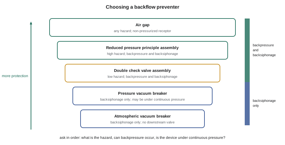
| Device | Protects against | Hazard | Notes |
|---|---|---|---|
| Air gap | Backsiphonage and backpressure | High | The surest method; needs a non-pressurized receptor |
| Reduced pressure principle assembly | Backsiphonage and backpressure | High | Relief port discharges water; needs drainage; tested annually |
| Double check valve assembly | Backsiphonage and backpressure | Low | Testable; common on fire services and low-hazard isolation |
| Pressure vacuum breaker | Backsiphonage only | High or low | Can be under continuous pressure; must be above the highest downstream outlet |
| Atmospheric vacuum breaker | Backsiphonage only | High or low | No valve downstream; not under pressure more than about 12 hours in 24 |
| Dual check valve | Backsiphonage and backpressure | Low, residential | Not testable; used at meters and on some boiler fills |
In the United States, devices are listed to national standards, and the IPC sets which device each connection needs. Many water systems, including Columbus, run cross-connection control programs that require testable devices on commercial and industrial services to be tested by a certified tester, usually every year. The exam asks which device fits a situation, how a reduced pressure assembly works and what a test confirms, rather than the details of any one city's program.
The reduced pressure principle assembly is the device exam writers like best, because its operation is a good test of understanding. It has two independent check valves with a relief valve between them. The zone between the checks is held at a lower pressure than the supply. If the first check leaks or the supply pressure falls, the relief valve opens and dumps water from the zone to atmosphere, so that water downstream can never reach the supply. Water discharging from the relief port is a sign that the assembly is working as designed or that a check is fouled, never a reason to plug the port.
A combined calculator
Maya's review calculator combines the three topics: the gas load at the meter, the hydronic flow for a zone, and the expansion tank size, with the classic error of using gauge pressure shown beside the right answer.
# Review calculator: gas load, hydronic flow, expansion tank
loads = {"furnace": 100_000, "water heater": 40_000, "range": 35_000}   # Btu/h
btu_per_ft3 = 1000
total = sum(loads.values())
print(f"Gas: {total:,} Btu/h = {total / btu_per_ft3:.0f} ft3/h at the meter")

for zone, dt in ((100_000, 20), (100_000, 40), (40_000, 20)):
    print(f"Hydronic: {zone:,} Btu/h at {dt} F drop -> {zone / (500 * dt):.1f} gpm")

v_sys, e, atm = 105, 0.030, 14.7         # gal, expansion, psi
p_fill, p_max = 12, 27.5                  # psig
right = v_sys * e / (1 - (p_fill + atm) / (p_max + atm))
wrong = v_sys * e / (1 - p_fill / p_max)
print(f"Expansion tank: {right:.1f} gal (absolute pressures); gauge-pressure error gives {wrong:.1f} gal")Gas: 175,000 Btu/h = 175 ft3/h at the meter Hydronic: 100,000 Btu/h at 20 F drop -> 10.0 gpm Hydronic: 100,000 Btu/h at 40 F drop -> 5.0 gpm Hydronic: 40,000 Btu/h at 20 F drop -> 4.0 gpm Expansion tank: 8.6 gal (absolute pressures); gauge-pressure error gives 5.6 gal
Common mistakes
MistakeSizing each gas branch from its own length.
InsteadUse the longest length from the meter to the farthest appliance for every section.
MistakeUsing gauge pressures in the expansion tank formula.
InsteadConvert fill and maximum pressures to absolute first.
MistakePlugging a dripping relief port on a reduced pressure assembly.
InsteadThe discharge shows the assembly is protecting the supply; test and repair it.
MistakeChoosing an atmospheric vacuum breaker where it is under continuous pressure.
InsteadUse a pressure vacuum breaker or another device rated for continuous pressure.
MistakeTreating a boiler fill as a harmless connection.
InsteadProtect it to the hazard; chemicals or glycol need a reduced pressure assembly.
Summary and key terms
- Gas loads add at the meter; the longest length method sizes every section from the length to the farthest appliance.
- Hydronic flow equals load divided by 500 times the temperature drop in gpm; doubling the drop halves the flow.
- Expansion tanks are sized from system volume, expansion and the ratio of absolute fill and maximum pressures.
- Low-pressure steam carries latent heat; traps, the Hartford loop and the low water cutoff are the key components.
- Backflow devices are chosen by hazard, by the type of backflow and by whether the device is under continuous pressure.
- The reduced pressure principle assembly vents its middle zone to atmosphere; an air gap is the most protective method.
- Longest length method
- Gas pipe sizing that uses the length to the farthest appliance for every section.
- Temperature drop
- The difference between supply and return water temperature across a load.
- Acceptance factor
- The fraction of an expansion tank's volume that can accept water, from the pressure ratio.
- Hartford loop
- A steam boiler return connection that prevents the boiler from draining if the return leaks.
- Backpressure
- Downstream pressure higher than supply pressure, which can push water backward.
Practice problems
Work each problem on paper first, then reveal the answer to check.
Appliances of 80,000, 50,000 and 30,000 Btu/h share a meter. What flow is that in ft³/h?
Show answer
160,000 / 1,000 = 160 ft³/h.
A 60,000 Btu/h zone at 20 °F drop needs what flow?
Show answer
60,000 / 10,000 = 6 gpm.
Why must expansion tank pressures be absolute?
Show answer
The air cushion obeys the gas laws, which use absolute pressure.
Which device protects a lawn irrigation system under continuous pressure from backsiphonage?
Show answer
A pressure vacuum breaker, installed above the highest sprinkler head.
Which device suits a boiler fill with antifreeze?
Show answer
A reduced pressure principle assembly, because the hazard is high and backpressure is possible.
Lesson quiz · 5 questions
Score 60% or more to complete this lesson.
Create a free account to save your progress, take quizzes and earn a certificate.