
PLB-310 · Lesson 5 of 12 · 22 min
Circulators and pump curves
In the Kingsway penthouse, Maya counted fourteen circulators, from small wet-rotor pumps on the boilers to large inline pumps on the risers, each with a nameplate, a tag and a curve on the submittal sheet. Luis handed her the curve for one of the riser pumps. "Most people think a pump makes pressure," he said. "In a closed loop, it does not lift water anywhere; the loop is already full. All it does is overcome friction. If you understand that, you understand pump curves." This lesson explains how circulators work, how to read a pump curve, how to find the flow a circulator will actually deliver in a system, and how modern variable-speed circulators save energy.
What a circulator does in a closed loop
In an open system, such as a well pump or a booster pump, the pump must lift water to a height and push it out of an outlet. In a closed hydronic loop, the water going up one pipe is balanced by water coming down another, so there is no net lift. The circulator only has to supply the energy lost to friction as water flows through pipes, fittings, valves, boilers and emitters. That energy is expressed as head, the height of water column it would support, in meters or feet.
Head and pressure are two ways of saying the same thing. One psi equals about 2.31 feet of water column. A circulator rated at 20 feet of head at zero flow can produce a pressure difference of about 8.7 psi across itself when its outlet is blocked, and less as flow increases.
Because the circulator only overcomes friction, the height of the building does not change the circulator's job. The same small circulator can serve a loop on one floor or a loop that rises three storys, if the friction is the same. What the height does change is the static pressure the system must be filled to, which Lesson 7 covers.
Types of circulators
Most residential and light commercial circulators are wet-rotor pumps: the motor's rotor spins inside the water, which lubricates and cools it, and there is no shaft seal to leak. They are quiet and need no maintenance, but they must be mounted with the motor shaft horizontal so the bearings stay submerged and air does not collect around the rotor. Larger systems use dry-rotor inline or base-mounted pumps with mechanical seals and separate motors.
Modern circulators use electronically commutated motors (ECM), also called high-efficiency or variable-speed circulators. They use far less electricity than the old permanent split capacitor motors and can change speed automatically. Many offer several operating modes: constant speed, constant pressure, which holds the head steady as zones open and close, and proportional pressure, which lowers the head as flow falls. Lesson 6 shows why constant or proportional pressure modes suit systems with zone valves.
Circulators for systems that take on fresh water, such as domestic hot water recirculation, must have bronze or stainless steel bodies to resist corrosion. Closed heating loops can use cast iron bodies, because the oxygen in the water is used up soon after filling.
Many circulators include an internal flow check, a small spring-loaded check valve that stops gravity circulation, also called ghost flow, when the circulator is off. Without it, hot water can rise by convection through an idle zone and overheat a room. In systems with several circulators, flow checks also prevent one circulator from pushing water backward through another.
Reading a pump curve
A pump curve shows the head a circulator produces at each flow rate. At zero flow the head is highest; this is called the shut-off head. As flow increases, the head falls, until at maximum flow the pump produces almost no head at all. Variable-speed circulators show a family of curves, one for each speed or mode setting.
A system curve shows the head the piping system needs at each flow rate. Friction rises roughly with the square of the flow: double the flow and the head loss rises about four times. At zero flow, the system needs no head at all, so the system curve starts at zero and rises steeply.
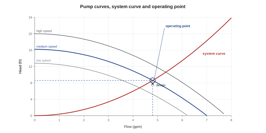
A circulator in a system always runs where the two curves cross, the operating point. It cannot run anywhere else: if it moved more water, the system would demand more head than the pump could give, and if it moved less, the pump would push harder than the system resists. Choosing a circulator means choosing one whose curve crosses the system curve at or just above the design flow.
Estimating the system's head loss
The head loss of a loop comes from three parts: the pipe itself, the fittings and valves, and the equipment such as the boiler or heat pump heat exchanger, coils and emitters. Pipe friction depends on the pipe's inside diameter, its roughness, its length and the flow. Fittings are converted to equivalent lengths of straight pipe and added to the measured length. Equipment manufacturers publish the pressure drop through their heat exchangers at various flows; a low-mass condensing boiler often has a much higher pressure drop than an old cast iron boiler, which is one reason the old circulator is rarely right for a new boiler.
Designers often use the Hazen-Williams equation for water piping, which relates head loss to flow, length, diameter and a roughness coefficient C, about 140 to 150 for copper and plastic and lower for old steel. It is accurate enough for water near room temperature and slightly conservative for hot water.
Velocity limits also guide pipe sizing. Water moving faster than about 4 ft/s in small pipes becomes noisy and can erode copper elbows over the years, while water moving slower than about 2 ft/s may not carry air bubbles along to the air separator. Most residential hydronic piping is sized to keep velocities between those limits.
Worked problem
Selecting the bungalow circulator
The bungalow's main loop carries 4.8 gpm. Grace measured 150 ft of 1-inch copper and added 50 ft of equivalent length for fittings and valves, 200 ft in total. The heat pump's heat exchanger and the boiler's piping together add 3.9 ft of head at that flow, and the radiators and their valves add 1.1 ft. What head does the circulator need?
Show solution
- Pipe friction from Hazen-Williams with C = 140, inside diameter 1.025 in: about 3.6 ft over 200 ft.
- Equipment: 3.9 ft. Radiators and valves: 1.1 ft.
- Total design head: 3.6 + 3.9 + 1.1 ≈ 8.6 ft at 4.8 gpm.
- Velocity in 1-inch copper at 4.8 gpm: about 1.9 ft/s, close to the lower limit, which is acceptable with a good air separator.
Answer: The circulator needs to deliver 4.8 gpm against about 8.6 ft of head. A small ECM circulator on its middle speed setting crosses that point with a little to spare.
# Operating point: where the pump curve meets the system curve
k_sys = 8.6 / 4.8 ** 2             # system curve H = k Q^2, through 8.6 ft at 4.8 gpm
def pump(q, speed):                # ECM circulator: shut-off 20 ft at full speed, affinity laws
    return 20.0 * speed ** 2 - 0.33 * q ** 2
for speed in (0.8, 0.9, 1.0):
    lo, hi = 0.0, 15.0
    for _ in range(60):
        q = (lo + hi) / 2
        lo, hi = (q, hi) if pump(q, speed) > k_sys * q * q else (lo, q)
print(f"speed {speed:.0%}: {q:.2f} gpm at {k_sys * q * q:.1f} ft head")speed 80%: 4.27 gpm at 6.8 ft head speed 90%: 4.80 gpm at 8.6 ft head speed 100%: 5.33 gpm at 10.6 ft head
The script finds the operating point by trying flows until the pump's head and the system's demand match. At full speed the circulator would push about 10 percent more than the design flow; at 90 percent speed it delivers the design flow almost exactly, and at 80 percent it falls short. Grace chose the setting closest to 90 percent and planned to confirm the temperature drop at start-up. Oversized circulators are as common as oversized boilers, and they waste electricity, cause velocity noise and reduce the temperature drop that condensing boilers and heat pumps need.
The affinity laws
When a circulator's speed changes, its flow, head and power change in a predictable way, described by the affinity laws. Flow is proportional to speed, head to the square of speed and power to the cube of speed. Slowing a pump to 80 percent speed cuts its flow to 80 percent, its head to 64 percent and its power to about 51 percent. That cube relationship is why variable-speed circulators save so much energy: most of the year a heating system needs only part of its design flow.
Circulators in series and parallel
Two identical circulators in series, one after the other, add their heads at each flow: the combined curve is twice as high. They suit systems with high head loss. Two in parallel, side by side, add their flows at each head: the combined curve is twice as wide. They suit systems that need high flow, and they provide redundancy if one fails. Kingsway's riser pumps are installed in parallel pairs, each sized for the full load, with one running and one on standby, alternating weekly so both stay in working order. That answered one of the questions Maya wrote down in Lesson 1.
Parallel circulators need check valves so the running pump does not push water backward through the idle one. In practice, the combined flow of two parallel pumps on a real system is less than double, because the system curve rises steeply: more flow needs much more head.
Installing a circulator
A circulator is installed with isolation valves or isolation flanges on both sides, so it can be replaced without draining the system. The arrow on the body shows the flow direction. The motor shaft must be horizontal, and the terminal box is turned so that condensation or a leak cannot run into it. The pump should have a straight run of pipe at its inlet where possible, and it should be located so that its inlet pressure stays well above the water's vapor pressure. If the inlet pressure falls too low, especially in hot systems or at the top of tall buildings, the water flashes into vapor bubbles inside the pump, a condition called cavitation that makes a gravel-like noise and destroys impellers.
Cavitation risk is the main reason for the rule repeated throughout this course: pump away from the point of no pressure change. A circulator whose inlet is at the expansion tank connection keeps its inlet at the fill pressure while adding its head to the rest of the system. A circulator pumping toward the expansion tank does the opposite, lowering the pressure at its inlet and in much of the system, which can draw in air through vents and fittings and cause cavitation.
Checking a circulator in the field
On a service call, the quickest check of a circulator is often the temperature drop across the loop it serves. If the supply and return differ by about the design drop while the heat source is firing steadily, the flow is close to design. A much larger drop means too little flow: a stuck valve, air, a clogged strainer or a failing pump. A very small drop with cold rooms points to a heat source that is not producing enough heat rather than a flow problem.
Many ECM circulators also display their power draw and an estimated flow on a small screen, and some connect to an app. These estimates are useful for a quick look but are calculated from motor data, not measured, so they can be off when the water is cold, contains glycol or carries air. Pressure gauges or test ports on each side of the circulator, read with the same gauge, give the head the pump is actually producing, which can be plotted on its curve to find the real flow. Luis taught Maya to trust two independent readings that agree more than a single display.
Common mistakes
MistakeReusing the old circulator with a new low-mass boiler.
InsteadRecalculate the head; condensing heat exchangers often have higher pressure drops.
MistakeChoosing the biggest circulator to be safe.
InsteadChoose one that crosses the system curve just above design flow; oversizing wastes power and causes noise.
MistakeMounting a wet-rotor circulator with the shaft vertical.
InsteadMount it with the shaft horizontal so the rotor stays flooded and lubricated.
MistakeLeaving out flow checks in multi-zone systems.
InsteadUse internal or separate flow checks to stop ghost flow and backflow through idle circulators.
MistakePumping toward the expansion tank.
InsteadPump away from the expansion tank connection to keep system pressure up and prevent cavitation.
Summary and key terms
- In a closed loop, a circulator only overcomes friction; it does not lift water.
- Head and pressure are equivalent: 1 psi is about 2.31 ft of water.
- The operating point is where the pump curve crosses the system curve.
- System head loss rises roughly with the square of flow and includes pipe, fittings and equipment.
- Keep velocities between about 2 and 4 ft/s in small hydronic piping.
- Affinity laws: flow varies with speed, head with speed squared, power with speed cubed.
- ECM circulators save energy and offer constant and proportional pressure modes.
- Install with isolation, the shaft horizontal, flow checks where needed, and pumping away from the expansion tank.
- Head
- The energy a pump adds to water, expressed as the height of a water column.
- Pump curve
- A graph of the head a pump produces at each flow rate.
- System curve
- A graph of the head a piping system needs at each flow rate.
- Operating point
- The flow and head at which a pump runs in a particular system.
- Wet-rotor circulator
- A pump whose rotor runs in the system water, with no shaft seal.
- ECM
- Electronically commutated motor: an efficient variable-speed motor.
- Cavitation
- The formation and collapse of vapor bubbles in a pump when its inlet pressure is too low.
- Ghost flow
- Unwanted gravity circulation through an idle zone.
Practice problems
Work each problem on paper first, then reveal the answer to check.
Why does a circulator in a closed loop not need to overcome the building's height?
Show answer
Water going up is balanced by water coming down; the pump only overcomes friction.
About how many feet of head is 4 psi?
Show answer
About 9.2 ft.
If the flow doubles, about how much does friction head rise?
Show answer
About four times.
A circulator slows to 50 percent speed. What happens to its power?
Show answer
It falls to about one eighth.
Why are parallel circulators fitted with check valves?
Show answer
So the running pump does not push water backward through the idle one.
What noise and damage does cavitation cause?
Show answer
A gravel-like noise and impeller erosion.
Lesson quiz · 5 questions
Score 60% or more to complete this lesson.
Create a free account to save your progress, take quizzes and earn a certificate.