
PLB-120 · Lesson 8 of 12 · 24 min
Why venting matters
Maya's first real lesson in venting came from a service call, not from the drawings. Grace Lin, Northbridge's service plumber, took her to an older apartment building where a tenant on the sixth floor complained that her bathroom sink gurgled and smelled whenever the neighbors upstairs flushed. Grace ran water upstairs, watched the trap on the sixth floor bob and drop, and found the cause on the roof: the stack vent had been capped years ago during a roof repair. Without air coming in at the top, every flush upstairs pulled the sixth-floor trap dry. Grace cut the cap off, and the gurgling stopped.
Lesson 7 showed that most trap seal losses are pressure problems. This lesson explains where those pressures come from, how vents control them, the main parts of a venting system, the limits on trap arms, and the rules for where vents terminate outdoors. Lesson 9 then covers the different ways of venting fixtures and how vents are sized.
Air in the drainage system
A drainage system is never just full of water. Most of its volume is air, and that air moves every time water flows. Water falling down a stack drags air down with it. Water running along a branch pushes air ahead of it and pulls air behind it. A large slug of water from a flushing toilet acts like a piston in the pipe. If air cannot move freely in and out of the system, these movements create pressure differences, and trap seals are what give way.
A trap seal is not strong. The weight of the water in the trap holds it in place, and the pressure needed to push or pull the seal out is only the pressure of a column of water as tall as the seal. A pressure difference of a fraction of an inch of water, far less than you could feel with your hand over a pipe, can break it.
Worked problem
How much pressure breaks a trap seal?
A trap has a seal depth of 2 inches. How much pressure difference across the seal would push or pull the water down to the dip?
Show solution
- Pressure of a water column: 2 inches of water column.
- Converting: 1 psi equals about 27.7 inches of water, so \(2 \div 27.7 \approx 0.072\) psi.
- For comparison, normal water supply pressure is around 50 to 80 psi; the seal resists about one thousandth of that.
Answer: Only about 0.07 psi, which is why drainage pressures must be kept very close to atmospheric.
Designers therefore try to keep the air pressure in the drainage system within a very narrow band around atmospheric pressure, typically within about the height of a small fraction of the trap seal. The venting system is how they do it: it connects the drainage piping to the outdoor air so that air can flow in where the pressure would drop and out where it would rise.
Where the pressures come from
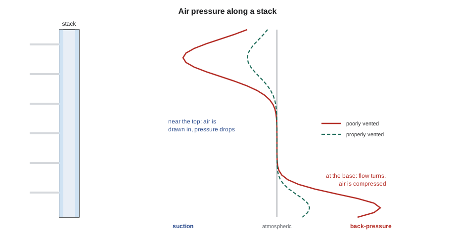
In a stack, the falling water pulls air down. Near the top, air is drawn in through the stack vent, and if the vent is undersized, long or blocked, the pressure in the upper part of the stack drops below atmospheric. Traps connected there are pulled toward the stack: this is induced siphonage.
At the base, the water slows and turns, the drain can briefly run full, and the air carried down with the water is squeezed. The pressure in the lower part of the stack and in the building drain rises above atmospheric. Traps connected there are pushed back toward the fixture: this is back-pressure. In tall buildings, the effect at the base can be strong enough to blow water out of floor drains and toilets on the lowest floors.
In a fixture drain, a fixture discharging its own water fills the trap arm and, as the slug runs down, pulls the seal after it. This is self-siphonage. It depends on the length and slope of the trap arm and how close the vent is to the trap.
The parts of a venting system
Venting terms are easy to confuse because several of them combine the same two words. These are the main ones:
- Stack vent: the extension of a soil or waste stack above the highest branch, up through the roof. It lets air into the top of the stack.
- Vent stack: a separate vertical vent pipe that runs beside a soil or waste stack through the building. It connects to the drainage stack at or near its base and to individual or branch vents on each floor, and it joins the stack vent above the highest fixture or goes through the roof on its own.
- Individual vent (or back vent): a vent connected to the trap arm of one fixture, rising to connect to a branch vent, vent stack or stack vent above the fixture's flood level.
- Branch vent: a horizontal vent that collects individual vents and connects them to a vent stack or stack vent.
- Relief vent: a vent that lets air move between a drainage pipe and the vent system to relieve pressure, for example at a stack offset, at the base of a tall stack, or at intervals in tall buildings.
- Vent header: a pipe that combines several vent stacks or stack vents before they pass through the roof, reducing the number of roof penetrations.
- Vent terminal: the open end of the vent piping outdoors, usually above the roof.
On Kingsway Tower, each soil stack has a vent stack beside it. On each floor, the suite's fixtures connect to vents that join the vent stack. The vent stack connects to the soil stack at the base and also through relief connections at intervals up the building, and the vent stacks and stack vents combine in vent headers in the roof space before passing through the roof in a small number of terminals.
Tall buildings need relief
In a tall building, the pressure swings along a stack grow with height and flow. A single vent connection at the top and bottom is not enough to keep the pressures in the middle of the stack under control. Codes therefore require relief connections between the drainage stack and the vent stack at intervals, typically every set number of branch intervals counting down from the top of the stack.
The IPC and the Ohio Plumbing Code require stacks with more than ten branch intervals to have a relief vent at every tenth interval counting down from the top floor, connected to the stack below the branch and to the vent stack above the floor. On Kingsway, the engineer has shown these relief connections at the required intervals.
Relief vents are also used at horizontal stack offsets, as lesson 4 explained, so that air can move around the offset, and at the base of tall stacks, where they let compressed air escape into the vent stack instead of pushing through the lowest traps.
Trap arms and distance to the vent
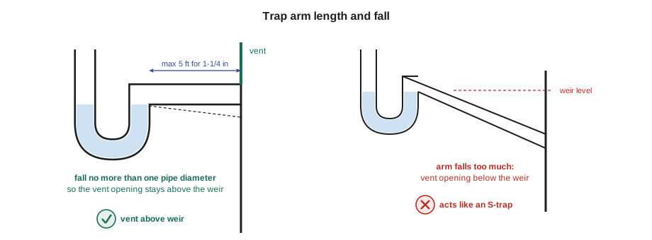
The trap arm is the part of the fixture drain between the trap's weir and the vent connection. Its length and slope decide whether the fixture will self-siphon. If the arm is too long or too steep, the slug of water running down it fills the pipe and pulls the seal out behind it. Codes therefore limit the length of the trap arm by pipe size and limit its total fall.
| Trap arm size | Practice maximum length | Typical slope |
|---|---|---|
| 1-1/4 in | 5 ft | 1/4 in per ft |
| 1-1/2 in | 6 ft | 1/4 in per ft |
| 2 in | 8 ft | 1/4 in per ft |
| 3 in | 12 ft | 1/8 in per ft |
| 4 in | 16 ft | 1/8 in per ft |
A second rule matters just as much: the vent connection must not be below the trap's weir, and the total fall of the trap arm should not be more than about one pipe diameter. If the trap arm falls more than its own diameter, the vent opening ends up below the level of the weir, and the trap arm acts like the long leg of a siphon. That is the hidden version of an S-trap.
Worked problem
Checking a lavatory trap arm
A lavatory in a Kingsway suite has a 1-1/4 inch trap arm 4 ft long at 1/4 inch per foot. Does it meet the practice length limit, and is its total fall within one pipe diameter?
Show solution
- Practice limit for 1-1/4 inch: 5 ft; \(4 < 5\), so the length is acceptable.
- Total fall: \(4 \times \tfrac{1}{4} = 1\) in.
- One pipe diameter: 1-1/4 in; \(1 < 1.25\), so the vent opening stays above the weir.
Answer: The trap arm meets both checks.
# Check trap arms against the practice table: length and total fall
LIMITS = {1.25: 5, 1.5: 6, 2: 8, 3: 12, 4: 16}      # feet

def check(size_in, length_ft, in_per_ft):
    fall_in = length_ft * in_per_ft
    ok_len = length_ft <= LIMITS[size_in]
    ok_fall = fall_in <= size_in
    return f"{size_in:4.2f} in, {length_ft:2d} ft at {in_per_ft:5.3f} in/ft: fall {fall_in:4.2f} in, length {'ok' if ok_len else 'TOO LONG'}, fall {'ok' if ok_fall else 'TOO MUCH'}"

for case in ((1.25, 4, 0.25), (1.5, 7, 0.25), (2, 8, 0.25), (3, 10, 0.125), (1.5, 6, 0.5)):
print(check(*case))1.25 in, 4 ft at 0.250 in/ft: fall 1.00 in, length ok, fall ok 1.50 in, 7 ft at 0.250 in/ft: fall 1.75 in, length TOO LONG, fall TOO MUCH 2.00 in, 8 ft at 0.250 in/ft: fall 2.00 in, length ok, fall ok 3.00 in, 10 ft at 0.125 in/ft: fall 1.25 in, length ok, fall ok 1.50 in, 6 ft at 0.500 in/ft: fall 3.00 in, length ok, fall TOO MUCH
Look at the last case in the output: a trap arm within the length limit can still fail if it is laid too steeply, because its total fall exceeds one pipe diameter. Keeping trap arms at the minimum slope is not laziness; it is what keeps the vent above the weir.
Vent terminals
Vents must end outdoors, where the air they carry, which smells of sewer, can disperse safely and where they cannot be blocked. Codes set rules for vent terminals that follow from those two aims:
- Height above the roof: the terminal must extend a set distance above the roof surface, more on roofs used as terraces or walkways, so that people are not exposed and snow does not cover it.
- Distance from openings: the terminal must be a set distance from windows, doors, air intakes and other openings into the building, or extend a set height above them, so that sewer air is not drawn back inside.
- Distance from property lines and walls: terminals must be kept away from neighboring property and from walls that could trap the air.
- Frost protection: in cold climates, moist warm air leaving a small vent can freeze and close the opening, so codes require vent terminals above a set size and may require increasing the size before the vent passes through the roof.
- No caps or screens that restrict airflow: decorative caps and covers can block the vent, as Grace's service call showed.
The Ohio Plumbing Code, following the IPC, sets the height of vent terminals above the roof, the distance from doors, windows and air intakes, the distance from property lines, and frost closure protection. On Kingsway, all terminals are well inside the roof area, away from the rooftop air handling units' intakes.
Vent pipe grade and connections
Vent pipes carry air, but they also collect condensation and occasionally water if a drain backs up. They must therefore be graded so that any water drains back to the drainage system by gravity, without dips or sags that could trap water and block the air. Horizontal vents are generally kept above the flood level rim of the fixtures they serve, so that if a drain blocks, waste water rises in the fixture before it can enter the vent, rather than flowing into the vent and using it as a drain.
Where a vent connects to a horizontal drain, it must take off from the top half of the drain, above its centerline, so that waste does not run into it. A vent taken off the side or bottom of a drain fills with water and solids and stops working.
Common mistakes
MistakeCapping or screening a vent terminal to keep out debris.
InsteadLeave vent terminals open and sized for frost protection; use only approved terminal fittings.
MistakeRunning a trap arm too steeply so the vent opening ends up below the weir.
InsteadKeep the total fall of the trap arm within one pipe diameter.
MistakeConnecting a vent to the bottom or side of a horizontal drain.
InsteadTake vents off above the centerline of the drain.
MistakeLeaving dips in horizontal vent piping.
InsteadGrade vents so water drains back to the drainage system.
MistakeAssuming a tall stack only needs vent connections at the top and bottom.
InsteadInstall relief connections at the intervals the code requires.
Summary and key terms
- Moving water drags and pushes air; without venting, the resulting pressures break trap seals.
- A 2-inch trap seal resists only about 0.07 psi, so drainage pressures must stay very close to atmospheric.
- Stacks see suction near the top and back-pressure near the base.
- Stack vents, vent stacks, individual and branch vents, relief vents and vent headers connect the system to outdoor air.
- Trap arms are limited in length and in total fall so the vent stays above the weir.
- Vent terminals must be high enough, far enough from openings and property lines, open and protected from frost.
- Stack vent
- The extension of a soil or waste stack above the highest branch, through the roof.
- Vent stack
- A vertical vent pipe running beside a drainage stack and connected to it at the base and at intervals.
- Individual vent
- A vent connected to the trap arm of a single fixture.
- Trap arm
- The part of a fixture drain between the trap weir and the vent connection.
- Vent terminal
- The open end of a vent pipe outdoors.
- Back-pressure
- Air pressure above atmospheric in a drain that can push a trap seal out into the fixture.
Practice problems
Work each problem on paper first, then reveal the answer to check.
Why can a very small pressure difference break a trap seal?
Show answer
The seal is held only by the weight of a couple of inches of water.
Where in a stack does induced siphonage usually occur, and why?
Show answer
Near the top, where air is drawn in through the stack vent and the pressure drops.
What is the difference between a stack vent and a vent stack?
Show answer
A stack vent is the extension of the drainage stack above the top branch; a vent stack is a separate vent pipe running beside the stack.
A 1-1/2 inch trap arm runs 5 ft at 1/4 inch per foot. Does it meet the practice length and fall checks?
Show answer
Yes: 5 ft is under 6 ft, and the 1-1/4 inch fall is under 1-1/2 inches.
Why must vents be taken off the top half of a horizontal drain?
Show answer
So waste does not flow into the vent and block it.
Why are vent terminals protected against frost?
Show answer
Moist air leaving the vent can freeze and close a small opening.
Lesson quiz · 5 questions
Score 60% or more to complete this lesson.
Create a free account to save your progress, take quizzes and earn a certificate.