
PLB-110 · Lesson 12 of 12 · 24 min
Layout, measuring, testing and inspection
By her third month, Maya was trusted to rough in a suite bathroom on the seventh floor of Kingsway Tower with Luis checking her work. She laid out the fixture locations from the drawings, set the closet flange and the drain branch, ran the PEX supplies from the manifold, put the system under test and called Luis to look. He checked her measurements against the drawings, sighted the slope on the branch, read the gauge and signed the test sheet. Then he told her that she had just done, in miniature, everything a plumber does on every job: lay it out, measure it, cut it, join it, support it, test it and record it.
This final lesson brings the course together. It covers layout from drawings, measuring and fitting allowances, rough-in dimensions, and the pressure and leak tests that every plumbing system must pass before an inspector will approve it.
Laying out from drawings
Plumbing layout starts with the drawings and the building's reference lines. On a large project, the surveyors mark gridlines and benchmark elevations on every floor, as TRD-103 described. Fixture locations are measured from gridlines, finished walls or column centers shown on the architectural drawings, and drain inverts and pipe elevations are measured from the floor benchmark.
A good layout routine is to mark the fixture centers and pipe routes on the floor or wall, check them against the architectural drawings (not just the plumbing drawings, which may be schematic), check for conflicts with framing, ductwork and other services, and confirm with the foreman before cutting holes. Laser levels and plumb lasers make it easy to transfer points from floor to ceiling and to check slope over long runs.
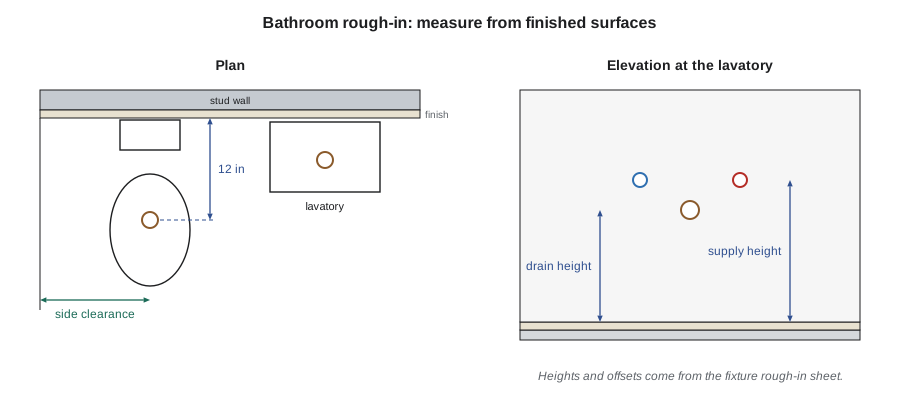
Remember that walls and floors have finishes that will be added later. A closet flange set to the bare slab will be too low once tile goes down; a fixture rough-in measured from a stud will be off once drywall and tile are on. Drawings and manufacturer's rough-in sheets say whether a dimension is from the finished floor or wall, and the plumber must allow for the finish thickness.
Rough-in dimensions
Every fixture has a rough-in sheet from its manufacturer showing where the drain and water supplies must be. The rough-in is the work done before walls are closed: drains, vents and supplies brought to the right place, capped and tested, ready for the fixtures to be set after finishes. Typical rough-in dimensions include:
Water closet: the outlet center is commonly 12 inches from the finished back wall, with the floor flange set level and at the right height for the finished floor. Side clearances from the center to a wall or other fixture are set by the code; the IPC requires at least 15 inches from the center to a side wall or partition.
- Lavatory: the drain stub in the wall, the supply stubs on either side, and heights that suit the vanity or wall-hung basin, all from the rough-in sheet.
- Bathtub and shower: the drain location from the tub manufacturer's sheet, and the mixing valve and showerhead heights from the specifications, adjusted for accessible units.
- Kitchen sink and dishwasher: drain and supply locations coordinated with the cabinet layout.
Accessible suites have different dimensions for heights, clearances and controls, set by the accessibility requirements in the building code and by the project. On Kingsway Tower, a number of suites are designed as barrier-free, and their rough-in sheets are kept separate so nobody uses a standard suite's dimensions by mistake.
Measuring pipe and fitting allowances
Pipe lengths are measured in a few standard ways. Center-to-center is the distance between the center lines of two fittings, which is what drawings and layouts usually give. End-to-end is the actual length of pipe. Between the two is the fitting allowance, also called take-off or make-up: the part of the center-to-center distance taken up by each fitting, after allowing for the depth the pipe goes into the fitting.
For socket fittings such as soldered copper, pressed copper or solvent-welded plastic, the take-off of a fitting is its center-to-end dimension minus the socket depth that the pipe enters. The cut length is then:
where C is the center-to-center distance and t is the take-off of each fitting. Fitting manufacturers publish take-off dimensions, and many plumbers keep a chart of the fittings they use most. For threaded pipe, lesson 8 showed the same idea using thread engagement.
Worked problem
Cutting copper for a supply branch
Two 3/4-inch wrought copper 90-degree elbows must have centers 30 in apart. The fitting chart gives a take-off of 7/16 in for each elbow. What length of tube should be cut?
Show solution
- Take-offs: \(\tfrac{7}{16} + \tfrac{7}{16} = \tfrac{7}{8}\) in.
- Cut length: \(30 - \tfrac{7}{8} = 29\tfrac{1}{8}\) in.
Answer: Cut 29-1/8 in of tube.
Offsets, which move a run sideways or up and down around an obstacle, use the right-triangle math from TRD-102. For a 45-degree offset, the travel (the center-to-center length of the diagonal piece) is the offset multiplied by about 1.414; subtract the take-offs of the two 45-degree fittings to get the cut length. Rolling offsets, which move a run in two directions at once, find the true offset first from the two directions, then apply the same rule.
import math
from fractions import Fraction
# Cut lengths from center-to-center measurements and fitting take-offs (inches)
def s16(x):
    f = Fraction(round(x * 16), 16); w, r = divmod(f, 1)
    return f"{w} {r}" if r else f"{w}"
takeoff = {"3/4 90": 7/16, "3/4 45": 3/16, "1/2 90": 5/16, "1/2 tee": 5/16}
pieces = [
    ("riser tee to first 90", 30, "1/2 tee", "1/2 90"),
    ("supply run",            72, "3/4 90", "3/4 90"),
]
for name, c, f1, f2 in pieces:
    print(f"{name:22s} cut {s16(c - takeoff[f1] - takeoff[f2])} in")
# a 45-degree offset of 10 in around a beam flange
offset = 10
travel = offset * math.sqrt(2)
print(f"45-degree offset travel {s16(travel)} in, cut {s16(travel - 2 * takeoff['3/4 45'])} in")riser tee to first 90 cut 29 3/8 in supply run cut 71 1/8 in 45-degree offset travel 14 1/8 in, cut 13 3/4 in
Measure twice, cut once is more than a saying in plumbing. A pipe cut short is wasted, and a pipe cut long is forced, which strains joints and supports. Mark cut lines clearly, keep measuring tapes in good condition, and work from the same reference throughout a run so small errors do not add up.
Testing new plumbing
Every new plumbing system is tested before it is concealed and before it is put in service. Tests prove that the joints are tight and the system will hold, and an inspector usually witnesses them or checks the record. Tests are done in stages: underground drainage before backfill, rough-in drainage and water piping before walls and ceilings are closed, and a final check when fixtures are set and the system is working.
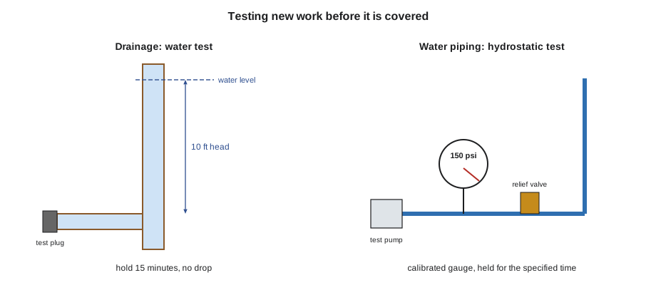
Drainage and vent piping is commonly given a water test: all openings are plugged, and the system is filled with water to a head of at least 10 feet above the highest joint being tested (or to the top of the section), held for at least 15 minutes, and checked for any drop in level or leaks. An air test at 5 psi held for 15 minutes is allowed as an alternative for some materials. Tall buildings are tested in sections so the lowest joints do not see too much pressure from the water column.
Water supply piping is given a pressure test, usually with water, at not less than the working pressure, held for a set time with no drop on the gauge and no visible leaks; the IPC also allows an air test of at least 50 psi for piping other than plastic. The specifications often set more: on Kingsway Tower they call for 150 psi for two hours, recorded on a test sheet.
Air testing deserves particular care. Compressed air stores a lot of energy, and if a fitting or plastic pipe fails under air pressure it can fail violently, throwing fragments. Many plastic pipe manufacturers prohibit testing their pipe with compressed air or gas, and safety rules on many sites forbid it. Use water where possible, follow the manufacturer's instructions, use a pressure relief valve on the test rig, never exceed the specified pressure, and keep people clear of plugged openings and test caps.
Test plugs and caps must be rated for the pressure and installed correctly. A test plug blown out of a pipe under a water column can injure someone and flood the floor below. Gauges must be accurate and readable at the test pressure, and many specifications require calibrated gauges.
When a test fails, find the leak before doing anything else: walk the piping, look and listen at every joint, and for water piping watch the gauge while isolating sections. Fix the cause, which might be an unsoldered joint, an unpressed fitting, a cracked fitting or a joint not given its cure time, and test again. Never adjust a gauge, top up a water test or shorten the time to make a failing test look like a pass. That is falsifying a record, and the leak will still be there when the ceiling is closed.
# Check a water supply pressure test log: any drop over the test period fails
log = [  # (minutes, psi)
    (0, 150.0), (15, 150.0), (30, 149.8), (45, 150.0), (60, 150.0), (90, 150.0), (120, 150.0),
]
start = log[0][1]
lowest = min(p for t, p in log)
tolerance = 0.5          # gauge reading tolerance in psi (example)
print(f"start {start} psi, lowest {lowest} psi over {log[-1][0]} minutes")
print("PASS" if start - lowest <= tolerance else "FAIL: find the leak before retesting")start 150.0 psi, lowest 149.8 psi over 120 minutes PASS
Temperature changes affect pressure tests. Water in a pipe exposed to the sun or a cold draft changes temperature during the test, and the pressure rises or falls with it even with no leak. Testers allow the system to stabilize before starting the clock, and note the conditions on the record.
Inspection, flushing and disinfection
When a stage is complete and tested, the inspector is called. Have the system under test before the inspector arrives, the permit card and approved drawings available, pipe markings visible and access to every part of the work. The inspector checks materials, sizes, slopes, venting, supports, protection, firestopping and the test, and either approves the stage or lists deficiencies to correct. Only after approval may the work be covered.
Before a new water system is put into use, it is flushed to remove debris, flux and cutting oil, and in larger buildings often disinfected with a chlorine solution held for a set time and then flushed, with water samples sent for testing. The IPC, the local health and building authorities and the specifications set the procedure, often by reference to recognized standards for disinfecting water piping.
Finally, the plumber's records go into the turnover package for the owner: test reports, inspection approvals, as-built drawings showing any changes, valve tags and charts showing what each valve controls, and manufacturers' manuals and warranties for fixtures and equipment. A future service plumber trying to find a shut-off at two in the morning will be grateful for every accurate record.
Bringing it together
Worked problem
Maya's bathroom rough-in from start to sign-off
List the steps Maya followed to rough in the seventh-floor suite bathroom, using what this course has covered.
Show solution
- Read the drawings, specifications and fixture rough-in sheets; confirm finishes and accessibility requirements.
- Lay out fixture centers from the finished-wall lines and gridlines; check for conflicts with framing and ducts; confirm openings with the foreman.
- Install the drain branch in the specified material with correct fittings for each change of direction, at the required slope, with cleanouts where required.
- Run vents to the vent stack and supplies from the manifold, choosing approved materials and joining methods; ream, clean and join correctly.
- Support everything at the required spacing, protect pipe through studs and from screws, and leave openings ready for listed firestop systems.
- Cap and test the drainage with a water test and the supplies with a hydrostatic test; record the results.
- Call for inspection, correct any deficiencies, and keep records for the turnover package.
Answer: Layout, materials, joining, support, protection, testing and records: every step of this course applied to one bathroom.
PLB-120 builds on this course with drainage and venting design, and PLB-130 with water supply. The materials, joints, supports and tests you have learned here are the foundation for both.
Common mistakes
MistakeMeasuring rough-in dimensions from the bare slab or stud.
InsteadMeasure from the finished floor and finished wall as the rough-in sheet specifies.
MistakeCutting pipe to the center-to-center distance.
InsteadSubtract the fitting take-offs to get the cut length.
MistakeAir testing plastic pipe against the manufacturer's instructions.
InsteadUse a water test, or follow the manufacturer's and site's rules exactly.
MistakeTopping up a water test or adjusting a gauge to pass.
InsteadFind and fix the leak, then retest honestly.
MistakeCovering work before the inspector approves it.
InsteadKeep each stage open until it is tested and approved.
Summary and key terms
- Lay out from gridlines, finished-wall lines and benchmarks, checking architectural drawings and conflicts before cutting.
- Rough-in dimensions come from fixture sheets and are measured from finished surfaces; accessible units have their own dimensions.
- Cut length equals center-to-center minus the take-offs of the fittings; offsets use right-triangle math.
- Drainage is commonly tested with water to a 10 ft head for 15 minutes; water piping with a test at not less than working pressure.
- Air testing is dangerous and often prohibited for plastics; use rated plugs, relief valves and accurate gauges.
- Inspection, flushing, disinfection and accurate records complete the job.
- Rough-in
- The plumbing installed before walls and floors are finished, ready for fixtures to be set later.
- Center-to-center
- The distance between the center lines of two fittings.
- Take-off
- The part of a center-to-center distance taken up by a fitting, after allowing for socket depth.
- Travel
- The center-to-center length of the diagonal piece in an offset.
- Water test
- A drainage test in which the system is filled with water to a set head and held for a set time.
- Hydrostatic test
- A pressure test of water piping using water, held for a set time with no drop.
Practice problems
Work each problem on paper first, then reveal the answer to check.
Why must a closet flange height allow for the floor finish?
Show answer
Because the flange must suit the finished floor level, which is higher than the bare slab once tile is installed.
Two elbows are 40 in apart center to center, with take-offs of 7/16 in each. What is the cut length?
Show answer
40 minus 7/8, which is 39-1/8 in.
What is the travel of a 45-degree offset of 12 in?
Show answer
12 times 1.414, about 17 in.
What is a common water test for drainage piping?
Show answer
Fill to at least 10 ft of head above the highest joint and hold for at least 15 minutes with no drop.
Why is air testing more dangerous than water testing?
Show answer
Compressed air stores much more energy, so a failure can be violent.
Name three items that go into the turnover package.
Show answer
Any three of test reports, inspection approvals, as-built drawings, valve charts and tags, and manufacturers' manuals and warranties.
Lesson quiz · 5 questions
Score 60% or more to complete this lesson.
Create a free account to save your progress, take quizzes and earn a certificate.