
PHYS-131 · Lesson 9 of 12 · 26 min
Alternating current circuits
The electricity grid delivers alternating current: in Canada and the United States, a sinusoidal voltage that reverses direction 60 times a second. AC won out over DC for power distribution because transformers (Lesson 7) can step its voltage up for efficient long-distance transmission and down for safe use, and because AC generators and induction motors are simple and robust. With AC, resistors are joined by two more circuit elements whose behavior depends on frequency: capacitors (Lesson 4) and inductors (Lesson 8). This lesson describes sinusoidal voltages and currents with RMS values and phasors, defines reactance and impedance, works through series RLC circuits and resonance, and explains real, reactive and apparent power and why utilities and industrial plants care so much about power factor. It closes with a brief look at three-phase power. ELE-203 develops AC circuit analysis fully.
Sinusoidal voltage and RMS values
An AC voltage is described by \(v(t) = V_p\sin(\omega t)\), with peak value \(V_p\), angular frequency \(\omega = 2\pi f\) and frequency f. Because the voltage spends much of its time below the peak, AC voltages and currents are quoted by their root-mean-square (RMS) values, the DC values that would deliver the same average power to a resistor. For a sinusoid,
North American household supply is 120 V RMS between a line and neutral (240 V across the two lines of a split-phase service) at 60 Hz; its peak is \(120\sqrt{2} = 170\) V. Meters, nameplates and electrical codes all use RMS values unless they say otherwise, but insulation and semiconductor ratings must withstand the peak.
Resistors, inductors and capacitors in AC
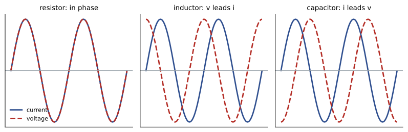
In a resistor, current and voltage rise and fall together: they are in phase. In an inductor, the voltage is \(L\,di/dt\), largest when the current is changing fastest, so the voltage leads the current by 90°. In a capacitor, the current is \(C\,dv/dt\), so the current leads the voltage by 90°. (A memory aid: ELI the ICE man: in an inductor, E (voltage) before I; in a capacitor, I before E.) The ratio of RMS voltage to RMS current for an inductor or capacitor is its reactance, measured in ohms:
Inductive reactance rises with frequency: an inductor passes DC freely but opposes rapid changes, which is why inductors (chokes) filter high-frequency noise from power lines. Capacitive reactance falls with frequency: a capacitor blocks DC but passes AC, which is why capacitors couple signals between amplifier stages and bypass noise to ground.
Phasors and impedance
Adding sinusoids of the same frequency but different phases is easy with phasors: rotating arrows whose length is the amplitude (or RMS value) and whose angle is the phase. Mathematically, a phasor is a complex number, and each circuit element has a complex impedance Z relating voltage and current phasors by Ohm's law, V = IZ:
using j for \(\sqrt{-1}\), as engineers do (i being reserved for current). Impedances combine exactly like resistances, in series and in parallel, so all the DC methods of Lessons 5 and 6, including Kirchhoff's laws, nodal analysis and Thévenin equivalents, carry over to AC with complex arithmetic. For a series RLC circuit:
where φ is the angle by which the voltage leads the current.
Worked problem
A series RLC circuit on the mains
A 10 Ω resistor, a 50 mH inductor and a 20 µF capacitor are in series across a 120 V, 60 Hz supply. Find the impedance, current and phase.
Show solution
- \(\omega = 377\) rad/s: \(X_L = 377 \times 0.050 = 18.8\) Ω and \(X_C = 1/(377 \times 20 \times 10^{-6}) = 132.6\) Ω.
- \(|Z| = \sqrt{10^2 + (18.8 - 132.6)^2} = 114.2\) Ω.
- \(I = 120/114.2 = 1.05\) A; \(\phi = \arctan(-113.8/10) = -85°\).
Answer: The circuit draws 1.05 A with the current leading the voltage by 85°: at 60 Hz it is dominated by the capacitor. Only the resistor dissipates power, 1.05² × 10 = 11 W, even though the supply delivers 126 volt-amperes.
Resonance
The inductive and capacitive reactances cancel at the frequency where \(\omega L = 1/(\omega C)\):
At this resonant frequency the impedance of a series RLC circuit falls to just R, the current is greatest and it is in phase with the voltage. Energy sloshes back and forth between the inductor's magnetic field and the capacitor's electric field, exactly as it moves between kinetic and potential energy in a mass-spring system (PHYS-130). The sharpness of the resonance is described by the quality factor \(Q = \omega_0L/R\): a high-Q circuit responds strongly only in a narrow band of frequencies.
import cmath, math

R, L, C, Vrms = 10.0, 0.050, 20e-6, 120.0      # series RLC on a 120 V supply
f0 = 1 / (2 * math.pi * math.sqrt(L * C))
print(f"Resonant frequency {f0:.1f} Hz")
for f in [60.0, f0, 400.0]:
    w = 2 * math.pi * f
    Z = R + 1j * (w * L - 1 / (w * C))        # complex impedance
    I = Vrms / Z
    phase = math.degrees(cmath.phase(Z))
    print(f"f = {f:6.1f} Hz: |Z| = {abs(Z):6.1f} ohm, phase {phase:+6.1f} deg, I = {abs(I):5.2f} A, P = {abs(I)**2 * R:6.1f} W")

# Power factor correction for a 5 kW motor load at 0.80 lagging on 240 V, 60 Hz
P, pf1, pf2, V, w = 5000.0, 0.80, 0.95, 240.0, 2 * math.pi * 60
Q1, Q2 = P * math.tan(math.acos(pf1)), P * math.tan(math.acos(pf2))
Cpf = (Q1 - Q2) / (w * V**2)
print(f"Reactive power {Q1 / 1000:.2f} kvar -> {Q2 / 1000:.2f} kvar: capacitor {Cpf * 1e6:.0f} uF")
print(f"Supply current {P / (V * pf1):.1f} A -> {P / (V * pf2):.1f} A")Resonant frequency 159.2 Hz f = 60.0 Hz: |Z| = 114.2 ohm, phase -85.0 deg, I = 1.05 A, P = 11.0 W f = 159.2 Hz: |Z| = 10.0 ohm, phase +0.0 deg, I = 12.00 A, P = 1440.0 W f = 400.0 Hz: |Z| = 106.2 ohm, phase +84.6 deg, I = 1.13 A, P = 12.8 W Reactive power 3.75 kvar -> 1.64 kvar: capacitor 97 uF Supply current 26.0 A -> 21.9 A
At its resonant frequency of 159 Hz, the same circuit draws 12 A, more than ten times the current at 60 Hz, and the voltages across the inductor and capacitor individually reach \(12 \times 50 = 600\) V, five times the supply. Resonance is the basis of radio tuning (a receiver selects one station by tuning an LC circuit to its frequency), of filters and of oscillators. It is also a hazard: harmonic currents from electronic loads can excite resonances between power factor correction capacitors and the inductance of the supply transformer, overloading the capacitors.
Power in AC circuits
When voltage and current are out of phase, part of the time energy flows into the circuit and part of the time it flows back out to the source. The average (real) power actually consumed is
measured in watts. The product \(S = V_{rms}I_{rms}\) is the apparent power, in volt-amperes (VA), and \(Q = V_{rms}I_{rms}\sin\phi\) is the reactive power, in volt-amperes reactive (var), the rate at which energy shuttles back and forth without being used. They form a right triangle: \(S^2 = P^2 + Q^2\). The power factor is \(\cos\phi = P/S\).
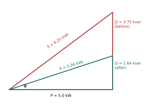
Utilities care about power factor because conductors, transformers and generators must carry the full current, set by apparent power, while customers are mainly billed for real power. Induction motors, transformers and fluorescent ballasts draw lagging reactive power; large industrial customers are often charged for low power factor, typically below 0.9. Adding capacitors, which supply leading reactive power, close to the loads cancels part of the motors' reactive power, a measure called power factor correction.
Worked problem
Correcting a motor's power factor
A 240 V, 60 Hz motor draws 5.0 kW at a power factor of 0.80 lagging. What capacitor raises the power factor to 0.95, and how much does the current fall?
Show solution
- Reactive power before: \(Q_1 = P\tan(\cos^{-1}0.80) = 5.0 \times 0.75 = 3.75\) kvar; after: \(Q_2 = 5.0\tan(\cos^{-1}0.95) = 1.64\) kvar.
- The capacitor must supply \(3.75 - 1.64 = 2.11\) kvar. Since \(Q_C = \omega CV^2\): \(C = 2110/(377 \times 240^2) = 97\) µF.
- Current before: \(5000/(240 \times 0.80) = 26.0\) A; after: \(5000/(240 \times 0.95) = 21.9\) A.
Answer: A 97 µF capacitor cuts the supply current by 16%, reducing losses in the cables (which scale with I²) by about 29% and freeing capacity in the supply. The motor itself is unaffected: it still receives the same voltage and does the same work.
Three-phase power
Large loads and the whole transmission network use three-phase power: three sinusoidal voltages of equal size, 120° apart. Three-phase systems deliver constant total power, rather than the pulsating power of a single phase, which lets motors run smoothly; they need less conductor material for the same power; and three-phase currents in stator windings create a rotating magnetic field, which is what makes induction motors start and run without brushes or commutators. In a balanced system, the line-to-line voltage is \(\sqrt{3}\) times the line-to-neutral voltage (for example 208 V and 120 V, or 600 V and 347 V in Canadian commercial buildings, and 480 V and 277 V in many US ones), and the total power is \(P = \sqrt{3}\,V_LI_L\cos\phi\). A 600 V motor drawing 50 kW at a power factor of 0.88 takes a line current of \(50\,000/(\sqrt{3} \times 600 \times 0.88) = 55\) A.
A balanced three-phase load draws equal currents in the three lines, and these currents add to zero at every instant, so the neutral conductor carries little or no current. Unbalanced single-phase loads spread across the phases, and harmonic currents from electronic equipment, can load the neutral heavily, which designers of large buildings must allow for.
Common mistakes
MistakeUsing peak values where RMS values are meant, or the reverse.
InsteadPower and nameplate values use RMS; insulation must withstand the peak, √2 times RMS.
MistakeAdding resistance and reactance as plain numbers.
InsteadCombine them as complex impedances: |Z| = √(R² + X²).
MistakeExpecting inductors and capacitors to consume real power.
InsteadIdeal L and C store and return energy; only resistance consumes it.
MistakeComputing power as V_rms I_rms when the load is reactive.
InsteadReal power is V_rms I_rms cos φ.
MistakeForgetting that voltages across L and C can exceed the supply at resonance.
InsteadEach can reach Q times the supply voltage; rate components accordingly.
Summary and key terms
- V_rms = V_p/√2; North American supply is 120/240 V RMS at 60 Hz, with a 170 V peak on 120 V.
- Voltage leads current by 90° in an inductor and lags by 90° in a capacitor.
- Reactances: X_L = ωL rises with frequency; X_C = 1/(ωC) falls.
- Complex impedances combine like resistances: series RLC has Z = R + j(ωL − 1/ωC).
- Resonance at f₀ = 1/(2π√(LC)) minimizes series impedance; Q = ω₀L/R sets sharpness.
- Real power P = VI cos φ, reactive Q = VI sin φ, apparent S = VI; power factor = cos φ.
- Capacitors correct lagging power factor; three-phase power uses P = √3 V_L I_L cos φ.
- RMS value
- The effective value of an alternating quantity, equal to the DC value giving the same power.
- Phasor
- A rotating arrow or complex number representing a sinusoid's amplitude and phase.
- Reactance
- The opposition of an inductor or capacitor to alternating current, in ohms.
- Impedance
- The complex ratio of voltage to current, combining resistance and reactance.
- Resonant frequency
- The frequency at which inductive and capacitive reactances cancel.
- Quality factor
- A measure of the sharpness of resonance.
- Real power
- The average power consumed, in watts.
- Reactive power
- Power that oscillates between source and load without being consumed, in var.
- Power factor
- The ratio of real to apparent power, cos φ.
- Three-phase power
- A system of three sinusoidal voltages 120° apart.
Practice problems
Work each problem on paper first, then reveal the answer to check.
Find the peak of a 240 V RMS supply.
Show answer
339 V.
Find the reactance of a 100 mH inductor at 60 Hz.
Show answer
37.7 Ω.
Find the reactance of a 10 µF capacitor at 60 Hz and at 6 kHz.
Show answer
265 Ω and 2.65 Ω.
A 30 Ω resistor is in series with X_L = 40 Ω. Find |Z| and φ.
Show answer
50 Ω, φ = +53.1°.
Find the resonant frequency of L = 10 mH and C = 1 µF.
Show answer
1/(2π√(10⁻⁸)) = 1.59 kHz.
What capacitance tunes a 250 µH coil to 1000 kHz?
Show answer
C = 1/(ω²L) = 101 pF.
A load draws 10 A at 120 V with φ = 30°. Find P, Q and S.
Show answer
P = 1039 W, Q = 600 var, S = 1200 VA.
What is the power factor of that load?
Show answer
0.866 lagging (if inductive).
A 10 kW load at PF 0.7 is corrected to 1.0. How much reactive power must the capacitor supply?
Show answer
10 tan(45.6°) = 10.2 kvar.
Find the line current of a 208 V three-phase heater drawing 15 kW (PF 1).
Show answer
15 000/(√3 × 208) = 41.6 A.
Lesson quiz · 5 questions
Score 60% or more to complete this lesson.
Create a free account to save your progress, take quizzes and earn a certificate.